A radio positioning system and positioning method thereof
A radio positioning and positioning request technology, applied in radio wave measurement systems, positioning, wireless communication, etc., can solve the problems of insufficient positioning accuracy, complex structure, and high bandwidth occupation
- Summary
- Abstract
- Description
- Claims
- Application Information
AI Technical Summary
Problems solved by technology
Method used
Image

Examples
Embodiment 1
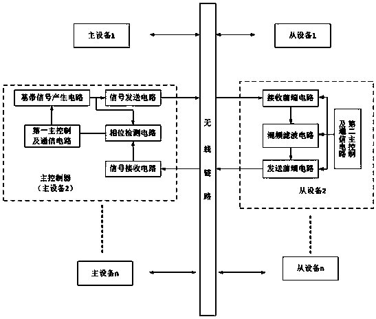
[0041] Such as figure 1 As shown, a radiolocation system includes at least three master devices and several slave devices;
[0042] Each master device communicates with each slave device through a wireless link, and one of the master devices serves as the master controller of the radio positioning system;
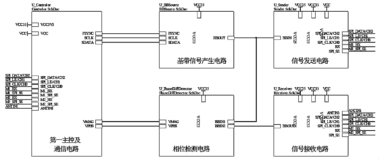
[0043] Each master device includes a baseband signal generating circuit, a signal sending circuit, a phase detection circuit, a first master control and communication circuit and a signal receiving circuit;
[0044] Each slave device includes a second master control and communication circuit, a receiving front-end circuit, a mixing and filtering circuit and a sending front-end circuit;
[0045] The output end of the baseband signal generation circuit is respectively connected with the input end of the signal transmission circuit and the first input end of the phase detection circuit, the output end of the signal transmission circuit is connected with the input end of the r...
Embodiment 2
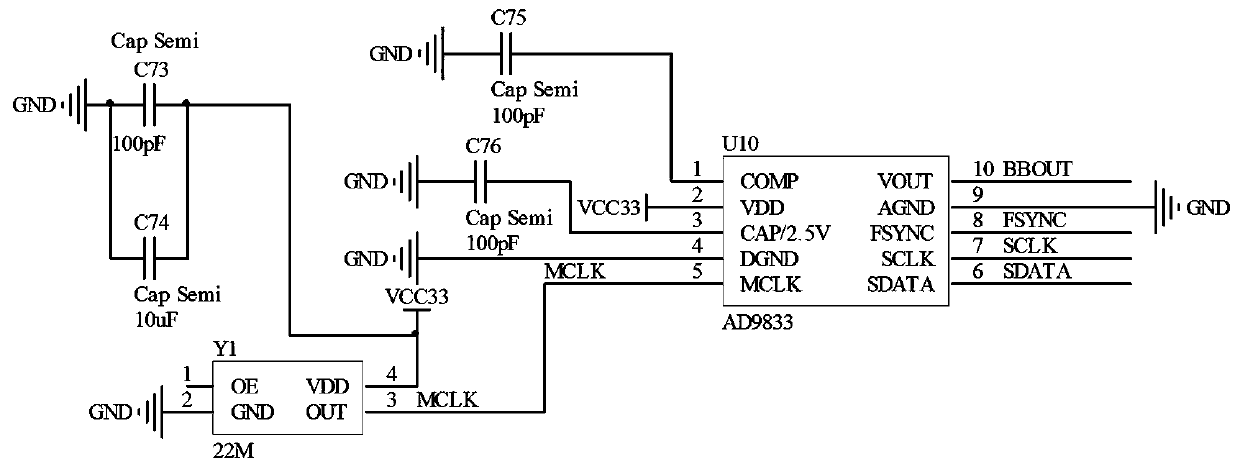
[0051] Such as image 3 As shown, the baseband signal generating circuit in the above-mentioned embodiment 1 includes a chip U10 of a programmable waveform generator;
[0052] The COMP pin of the chip U10 is connected to the ground capacitor C75;
[0053] The VDD pin of the chip U10 is connected to the 3.3V power supply;
[0054] The CAP pin of the chip U10 is connected to the ground capacitor C76;
[0055] The DGND pin of chip U10 is grounded;
[0056] The MCLK pin of the chip U10 is connected to the OUT pin of the crystal oscillator Y1;
[0057] The VOUT pin of the chip U10 is used as the output terminal BBOUT of the baseband signal generating circuit to be respectively connected to the input terminal BBIN of the signal transmission circuit and the first input terminal BBIN1 of the phase detection circuit;
[0058] The AGND pin of chip U10 is grounded;
[0059] The FSYNC pin of the chip U10 is connected to the first main control and communication circuit;
[0060] The ...
Embodiment 3
[0067] The signal transmission circuit in the above-mentioned embodiment 1 includes a chip U9 for signal transmission, a first filter sub-circuit and a transmission antenna sub-circuit;
[0068] in such as Figure 4 In the peripheral circuit of the chip U9 shown, the GND pin of the chip U9 is grounded;
[0069] The SPI_SE pin of the chip U9 is respectively connected to the grounding resistor R34 and the first main control and communication circuit;
[0070] The S pin of the chip U9 is connected to the grounding resistor R33;
[0071] The BX pins of the chip U9 are respectively connected to one end of the resistor R32 and the first main control and communication circuit, and the other end of the resistor R32 is connected to the 3.3V power supply;
[0072] The SPIDATA / CS0 pins of the chip U9 are respectively connected to one end of the resistor R31 and the first main control and communication circuit, and the other end of the resistor R30 is connected to the 3.3V power supply;...
PUM
 Abstract
Description
Claims
Application Information
 - R&D
- Intellectual Property
- Life Sciences
- Materials
- Tech Scout
- Unparalleled Data Quality
- Higher Quality Content
- 60% Fewer Hallucinations
Browse by: Latest US Patents, China's latest patents, Technical Efficacy Thesaurus, Application Domain, Technology Topic, Popular Technical Reports.
© 2025 PatSnap. All rights reserved.Legal|Privacy policy|Modern Slavery Act Transparency Statement|Sitemap|About US| Contact US: help@patsnap.com