
Temperature control system and method for controlling temperature of tested equipment

A technology for equipment under test and control system, applied in control/regulation system, temperature control, non-electric variable control, etc., can solve problems such as affecting the accurate temperature of the circuit board, affecting the working parameters of the circuit board, and difficult to strictly control the DUT, etc.

Active Publication Date: 2020-05-22
衍昌电子科技(东莞)有限公司
View PDF5 Cites 1 Cited by
  • Summary
  • Abstract
  • Description
  • Claims
  • Application Information

AI Technical Summary

Problems solved by technology

[0003] Most of the existing test systems are equipped with a heating plate that is in direct contact with the DUT (device under test). There is a fixed cooling plate, and an evaporator is installed on one side of the cooling plate. The cooling plate is cooled by the evaporator, and then the temperature of the heating plate is lowered by using the cooling plate, so as to achieve the purpose of cooling the DUT; but the evaporators are all Cooling by refrigerant evaporation and heat absorption, such as the integrated circuit temperature control system mentioned in the patent application number 201410832160.2, uses Peltier elements to cool the heat-conducting silica gel, and the heat-conducting silica gel cools the integrated circuit. The cooling method not only has limited cooling capacity, but also is difficult to achieve the effect of strictly controlling the DUT temperature; therefore, the accurate temperature of the circuit board is particularly important for the working parameters (current, voltage) of the circuit board, and in conventional temperature tests, usually accompanied by With the change of humidity, if the humidity is too high, dew may condense on the circuit board, which will not only affect the accurate temperature of the circuit board, but also affect the tested working parameters of the circuit board

Method used


Image

  • Temperature control system and method for controlling temperature of tested equipment
  • Temperature control system and method for controlling temperature of tested equipment
  • Temperature control system and method for controlling temperature of tested equipment

Examples


Embodiment 1

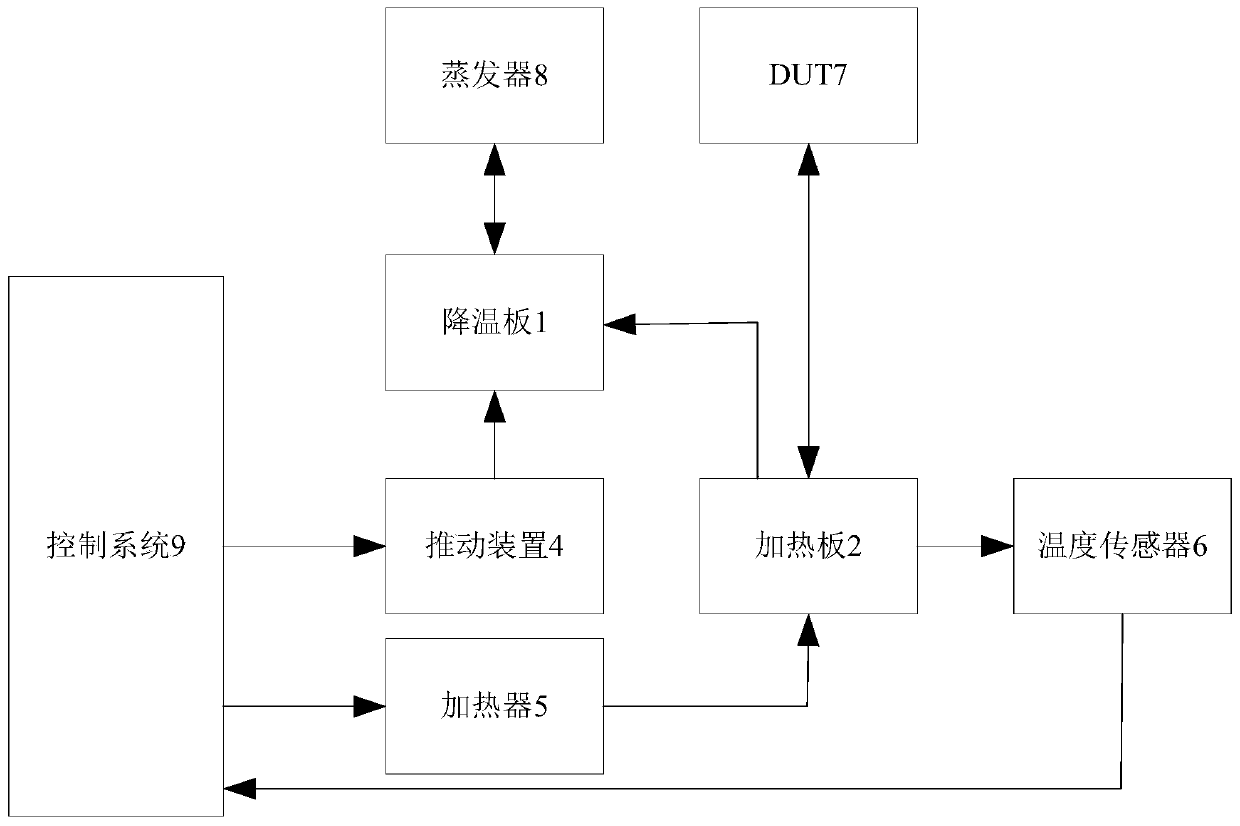
[0066] Embodiment 1: the test temperature of DUT7 can be set to be -45 degrees Celsius to 150 degrees Celsius, when the temperature needs to be adjusted to 150 degrees Celsius, the control system 9 controls the heater 5 to work, and the heater 5 increases the temperature of the heating plate 2, and the cooling at this time Under the elastic force of the bias spring, the plate 1 is away from the heating plate 2, forming a gap between the heating plate 2 and the cooling plate 1; on the contrary, if the temperature needs to be adjusted to -45 degrees Celsius, the control system 9 first controls the heater 5 Stop working, and then control the sharp moving device to push the cooling plate 1 to move towards the heating plate 2. When the cooling plate 1 approaches but does not touch the heating plate 2, as the distance decreases, the heat conduction rate increases; After being in contact with the heating plate 2, the pushing device 4 continues to apply pressure. Since the surface of t...

Embodiment 2

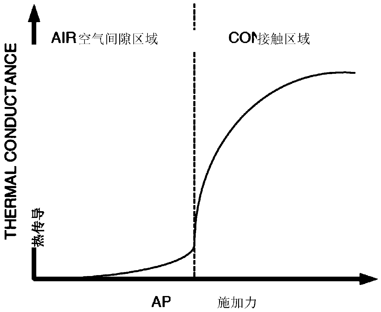
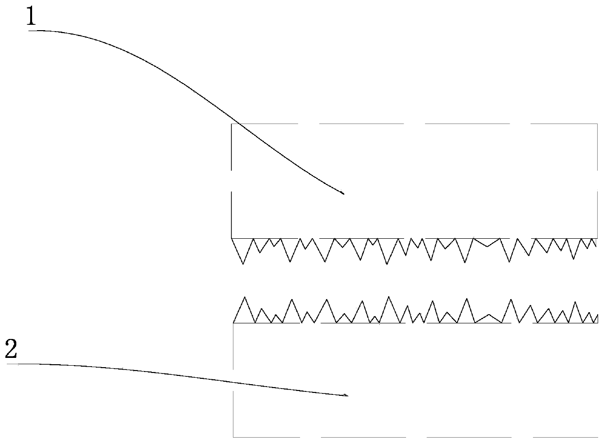
[0067] Example 2: see figure 2 , the relationship between heat conduction and force is characterized in two different regions, the first region on the left is the "air gap region", the second region on the right is the "contact region", in the air gap region, the force can always increase Until the bias spring is compressed into the first spring groove and the second spring groove, that is, the gap distance between the heating plate 2 and the cooling plate 1 is 0 at this time, and in the contact area, the heat conduction rate is determined by the cooling plate 1 to the heating plate 2 The heat absorbed by cooling plate 1 from heating plate 2 is determined by the temperature of cooling plate 1 and the heat conduction rate between cooling plate 1 and heating plate 2, please continue to refer to figure 2 , the left side is the heat conduction rate before the cooling plate 1 touches the heating plate 2. As the applied force F reaches a critical value, that is, the applied force>...


PUM

PropertyMeasurementUnit
Thicknessaaaaaaaaaa

Abstract

The invention discloses a temperature control system and method for controlling the temperature of tested equipment. The system comprises a heating plate which is used for heating the tested equipment; a temperature sensor which is used for sensing the temperature of the heating plate; a cooling plate which is used for cooling the heating plate, wherein the temperature of the cooling plate is lower than that of the heating plate; a pushing device which is connected with the cooling plate and used for controlling the cooling plate to move so as to control the heat conduction rate between the cooling plate and the heating plate; and a control system which is electrically connected with the temperature sensor and receives signals of the temperature sensor so as to control the pushing device to move. When the temperature sensor obtains temperature information of the heating plate by detection, the control system responds to the temperature information to control the pushing device to moveso as to control the temperature of the heating plate; the pushing device controls the cooling plate to move, so that the heat conduction rate of the heating plate and the cooling plate is controlled,and the effects of accurately controlling the temperature and being good in refrigerating effect are achieved.

Description

technical field [0001] The invention relates to the field of tested equipment, in particular to a temperature control system and method for controlling the temperature of the tested equipment. Background technique [0002] An integrated circuit is a miniature electronic device or component that interconnects transistors, resistors, capacitors, inductors and other components and wiring required in a circuit by a certain process, and is fabricated on a small or several small semiconductor chips or media. On the substrate, and then encapsulated in a tube shell, it becomes a microstructure with the required circuit function; the performance of integrated circuits is not static, and temperature is an important factor affecting the performance of integrated circuits. With the change of temperature, the performance of integrated circuits Conductivity, limit voltage, limit current, and switching characteristics will all change accordingly; therefore, it is necessary to test the temp...

Claims


Application Information

Patent Timeline
IPC IPC(8): G05D23/22
CPCG05D23/22
Inventor 蒋上明
Owner 衍昌电子科技(东莞)有限公司
Learn More