Cleaning device for coal cinder furnace in gas station

A technology for cleaning devices and gas stations, applied in the field of gas stations, can solve the problems of time-consuming and laborious cleaning inside the combustion chamber, occupying the combustion space inside the combustion chamber, and inability to completely remove coal slag, so as to save heat loss, improve production efficiency, and improve The effect of thermal insulation

Inactive Publication Date: 2020-05-22
广东粤辰新太智造有限公司
View PDF8 Cites 0 Cited by
  • Summary
  • Abstract
  • Description
  • Claims
  • Application Information

AI Technical Summary

Problems solved by technology

[0003] In the process of using the coal gasifier to burn coal to produce gas in the gas station, it is necessary to burn coal inside the combustion chamber to generate combustible gas, and after the coal is burned, the cinder needs to be discharged, but in the cinder discharge system, the combustion chamber There will still be residual phenomena in the interior of the combustion chamber, so the internal cinders cannot be completely removed during combustion, occupying the combustion space inside the combustion chamber. At the same time, the cleaning of the interior of the combustion chamber is time-consuming and laborious, which not only increases labor intensity, but also reduces work. Efficiency, unable to meet current usage needs

Method used


Image

  • Cleaning device for coal cinder furnace in gas station
  • Cleaning device for coal cinder furnace in gas station
  • Cleaning device for coal cinder furnace in gas station

Examples


Embodiment Construction

[0022] The following will clearly and completely describe the technical solutions in the embodiments of the present invention with reference to the accompanying drawings in the embodiments of the present invention. Obviously, the described embodiments are only some, not all, embodiments of the present invention. Based on the embodiments of the present invention, all other embodiments obtained by persons of ordinary skill in the art without making creative efforts belong to the protection scope of the present invention.

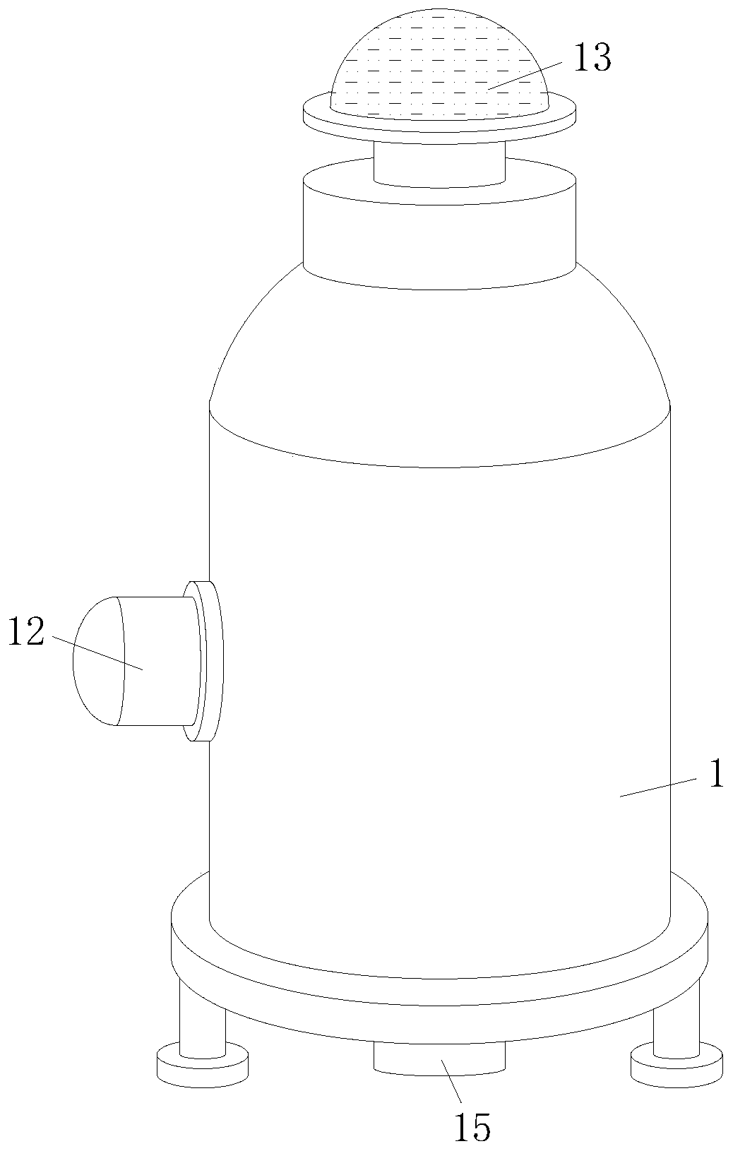
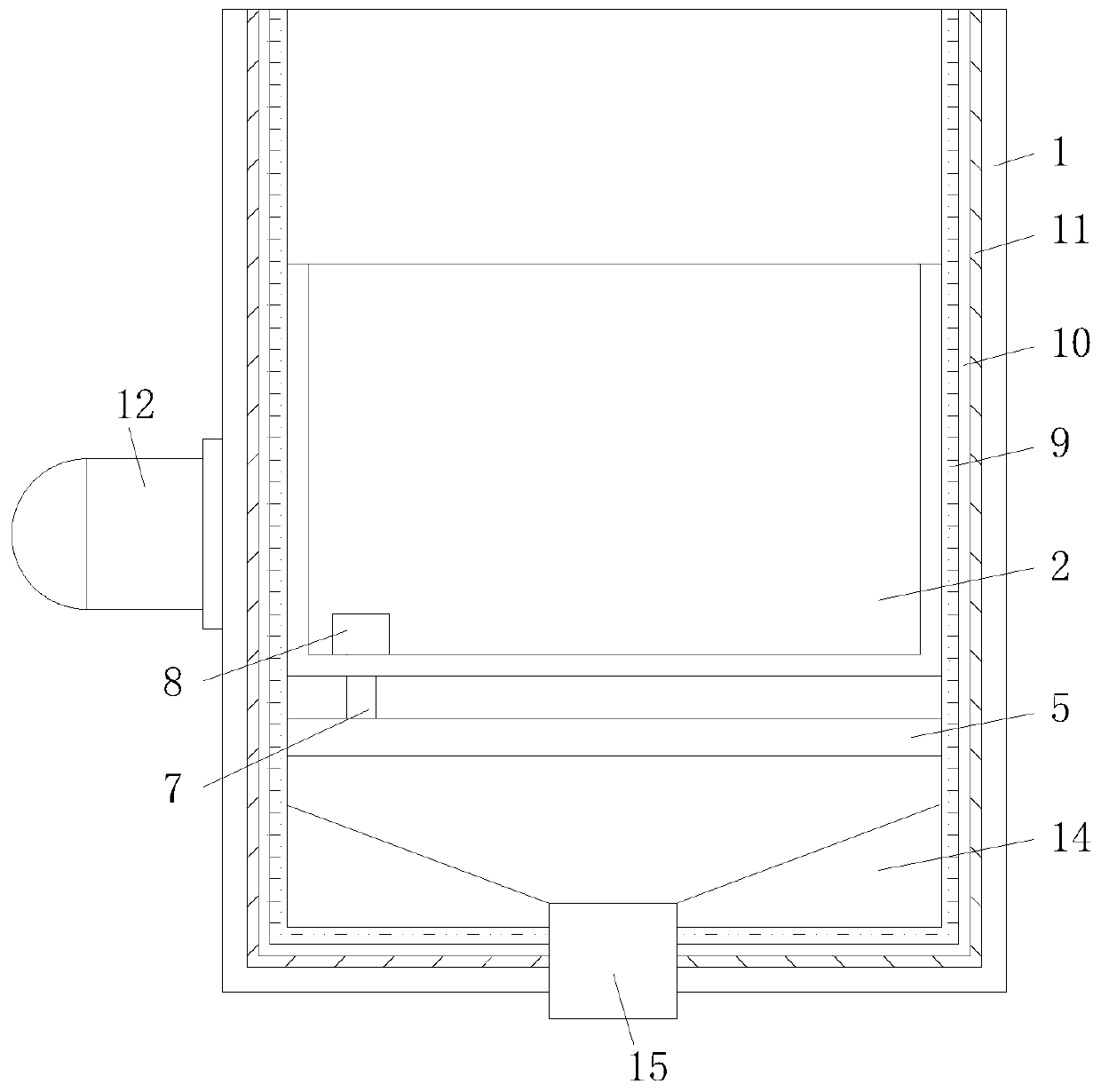
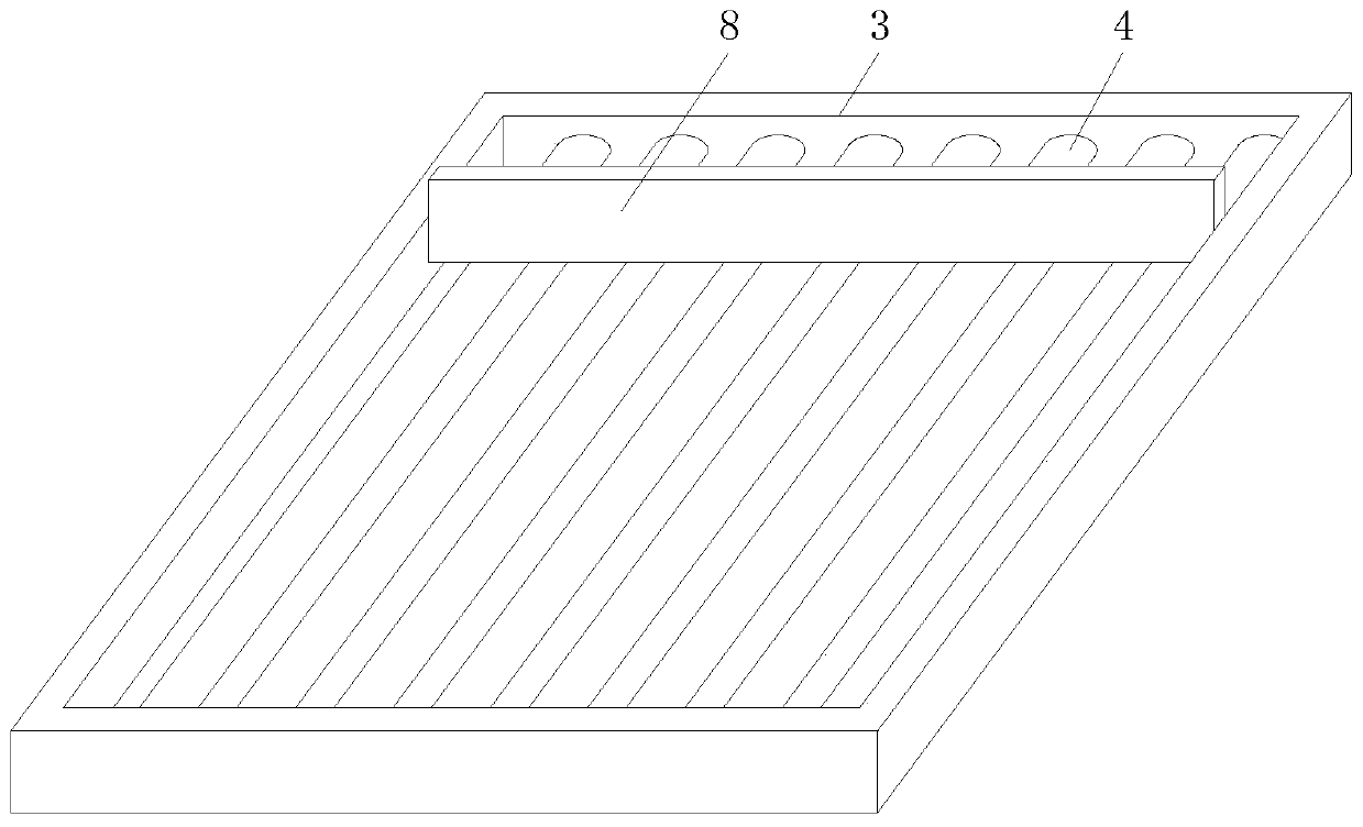
[0023] see Figure 1-4 , the present invention provides a technical solution: a cleaning device for coal gas station cinder furnace, including a furnace body 1, a combustion chamber 2, a mounting frame 3, a grid rod 4, a linear guide rail 5, an electric push rod 6, a connecting Rod 7, scraper 8, refractory insulation layer 9, asbestos insulation layer 10, light insulation layer 11, rock wool board 12, chimney 13, guide foundation 14 and gravity lock wind ash r...


PUM


Abstract

The invention relates to the technical field of gas stations, in particular to a cleaning device for a coal cinder furnace in a gas station. The cleaning device comprises a furnace body, a combustionchamber, an installation frame, grating rods, a linear guide rail, an electric push rod, a connecting rod, a scraping plate, a fire-resistant heat insulation layer, an asbestos heat insulation layer,a light heat insulation layer, a rock wool plate, a chimney, a guide base and a gravity air-lock ash discharge valve, wherein the combustion chamber is fixedly installed inside the furnace body; the periphery of the middle position at the bottom of the combustion chamber is fixedly connected with the periphery of the installation frame; the two sides of the inner wall of the installation frame arerespectively and fixedly connected with the two ends of each grating rod; and the two ends of the linear guide rail are respectively and fixedly connected with the two sides of the inner wall of thefurnace body. According to the cleaning device, the purpose of automatically removing coal slag in the interior of the combustion chamber is achieved, so that the interior of the combustion chamber isin a tidy state, the coal slag residue phenomenon is avoided, meanwhile, the labor intensity is reduced, the working efficiency is improved, the heat insulation effect of the furnace body is improved, and the energy consumption is reduced.

Description

technical field [0001] The invention relates to the technical field of gas stations, in particular to a cleaning device for cinder furnaces in gas stations. Background technique [0002] The gas station is mainly composed of a gas generator, a pipeline system, a gas treatment system, a circulating water system, and a monitoring system. The gas station mainly produces gas through the gas generator, with tar attached. Phenol water. And a small amount of hydrogen sulfide output. Since there are many kinds of gas furnaces, and their designs are not the same, there will be some differences between various gas stations after they are built. Because its production is very dangerous, the gas station is equipped with a safety cooperation system such as a coal defense station. [0003] In the process of using the coal gasifier to burn coal to produce gas in the gas station, it is necessary to burn coal inside the combustion chamber to generate combustible gas, and after the coal i...

Claims


Application Information

Patent Timeline
Patent Type & Authority Applications(China)
IPC IPC(8): F23J1/06
CPCF23J1/06
Inventor 刘加方吕永湛杨茂
Owner 广东粤辰新太智造有限公司
Why Eureka
Try Eureka