Eureka AIR delivers breakthrough ideas for toughest innovation challenges, trusted by R&D personnel around the world.

Bending auxiliary equipment for bamboo fiber board

An auxiliary equipment, bamboo fiber technology, applied in the direction of unloading equipment, sawing equipment, mechanical equipment, etc., can solve the problem that bamboo fiber board cannot be automatically used, cannot be operated by one person, pushed away, etc., to improve equipment practicability, Reduce the operation steps and avoid the effect of sliding left and right

Active Publication Date: 2020-05-22
ZHEJIANG WEILAODA IND & TRADING CO LTD
View PDF11 Cites 8 Cited by
  • Summary
  • Abstract
  • Description
  • Claims
  • Application Information

AI Technical Summary

Problems solved by technology

[0005] In order to overcome the shortcomings of being unable to be operated by a single person and unable to automatically push the bamboo fiber board away, the technical problem to be solved is: to provide a bamboo fiber board bending auxiliary equipment that can be used by a single person and can automatically push the bamboo fiber board away

Method used


Image

  • Bending auxiliary equipment for bamboo fiber board
  • Bending auxiliary equipment for bamboo fiber board
  • Bending auxiliary equipment for bamboo fiber board

Examples


Embodiment 1

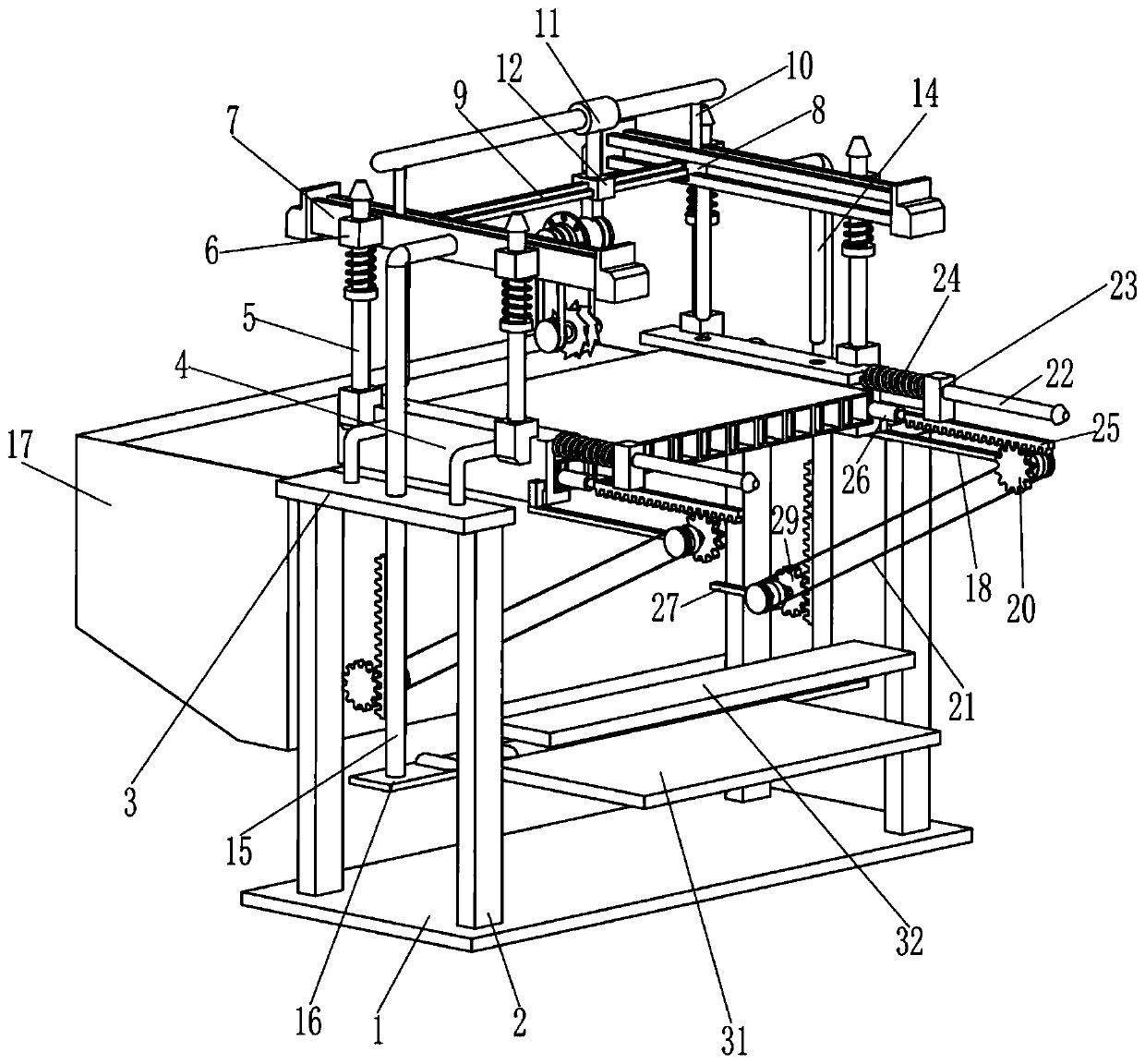
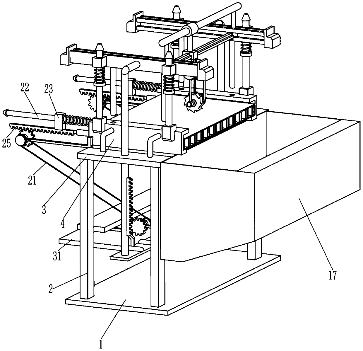
[0021] A kind of bamboo fiber board bending auxiliary equipment, such as Figure 1-4 As shown, it includes bottom plate 1, support rod 2, mounting frame 3, guide plate 4, guide rod 5, reset block 6, guide rail 7, guide block 8, slide rail 9, T-shaped frame 10, sliding sleeve 11, slider 12. Driving motor 1301, bearing housing 1302, first rotating shaft 1303, cutter 1304, transmission assembly 1305, rubber pressing rod 14, pull rod 15, pedal 16 and receiving hopper 17, support rods 2 are provided around the top of bottom plate 1, front and rear A mounting frame 3 is provided between the tops of two adjacent support rods 2, a guide plate 4 is provided on the mounting frame 3, and guide rods 5 are provided on both sides of the top of the guide plate 4, and a reset block is slidably connected to the guide rod 5 6. A guide rail 7 is provided on the inner side of the reset block 6 between the two adjacent parts. The guide rail 7 is slidably connected with the guide block 8. There is ...

Embodiment 2

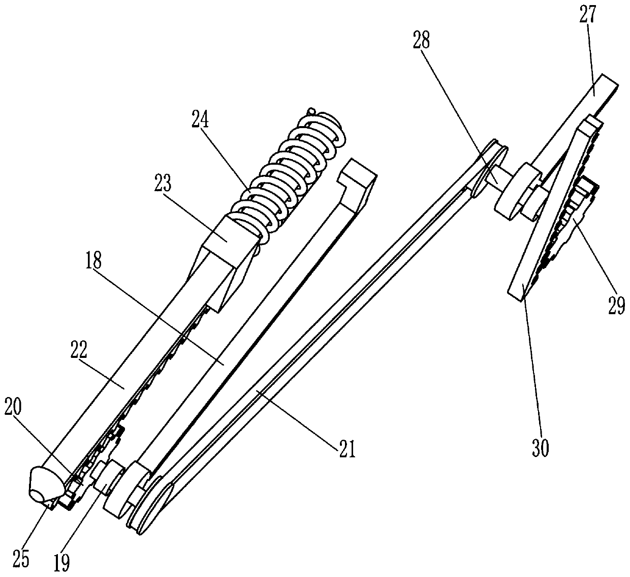
[0024] On the basis of Example 1, such as Figure 1-3 As shown, it also includes a first mounting seat 18, a one-way transmission shaft 19, a first drive gear 20, a drive assembly 21, a sliding rod 22, a guide sleeve 23, a compression spring 24, a first rack 25, a push rod 26, The second mounting base 27, the second rotating shaft 28, the second drive gear 29 and the second rack 30, the mounting frame 3 is provided with a first mounting base 18, and the first mounting base 18 is rotatably connected with a one-way transmission shaft 19 One end of the one-way transmission shaft 19 is provided with a first drive gear 20, the other end of the one-way transmission shaft 19 is connected with a drive assembly 21, one side of the installation frame 3 is provided with a sliding rod 22, and the sliding rod 22 is slidably connected with a guide sleeve 23 A compression spring 24 is connected between the guide sleeve 23 and the installation frame 3, the bottom of the guide sleeve 23 is pro...


PUM


Abstract

The invention relates to bending auxiliary equipment, in particular to bending auxiliary equipment for a bamboo fiber board. The technical aim of the bending auxiliary equipment for the bamboo fiber board is that one-man operation and using can be achieved, and the bamboo fiber board can be automatically pushed away. The bending auxiliary equipment for the bamboo fiber board comprises a bottom plate, supporting rods, mounting frames, guiding plates and the like; and the supporting rods are arranged on the periphery of the top of the bottom plate correspondingly, the tops of the adjacent supporting rods between the front part and the rear part are jointly provided with the corresponding mounting frames, and the guiding plates are mounted on the mounting frames. Through rubber pressure rods,when the equipment conducts cutting operation, the bamboo fiber board can be effectively fixed to be prevented from sliding left and right under the action of a cutter, and a stable operation environment is provided for a worker.

Description

technical field [0001] The invention relates to a bending auxiliary device, in particular to a bamboo fiberboard bending auxiliary device. Background technique [0002] Bamboo fiberboard is a kind of wood-based panel. It has the advantages of sound insulation, green environmental protection and no pollution. It is widely used in the process of home decoration. Its bending process, rather than cutting and assembling, because the bamboo fiber board needs to be cut and separated on one side when bending the bamboo fiber board, the operation steps are more complicated, and it requires the cooperation of multiple people, which is time-consuming and laborious. [0003] Chinese invention document "CN205552193U", on September 7, 2016, disclosed a trimming mechanism of a bamboo fiberboard dry paint edge wrapping machine, hereinafter collectively referred to as practical one, and the main technical point of practical one is how to solve the problem of cleaning grinding debris , and d...

Claims


Application Information

Patent Timeline
IPC IPC(8): B27B5/075B27B5/29B27B29/02B27B31/08B27J1/00
CPCB27B5/075B27B5/29B27B29/02B27B31/08B27J1/00
Inventor 黄春英
Owner ZHEJIANG WEILAODA IND & TRADING CO LTD
Why Eureka
Eureka Blog
Learn More