
Device for automatically assembling seat belt retractor

A safety belt retractor and automatic assembly technology, applied in assembly machines, metal processing equipment, metal processing, etc., can solve the problems of low manual assembly efficiency, high connection reliability, and high cost, and achieve good market application value , Improve assembly efficiency and reduce the effect of manual participation

Active Publication Date: 2020-05-22
XUCHANG UNIV
View PDF8 Cites 5 Cited by
  • Summary
  • Abstract
  • Description
  • Claims
  • Application Information

AI Technical Summary

Problems solved by technology

There is a ratchet mechanism inside the retractor. Under normal circumstances, the occupant can pull the webbing freely and at a constant speed on the seat, but once the continuous pulling process of the webbing from the retractor stops or when the vehicle encounters an emergency, the ratchet mechanism will work. The locking action will automatically lock the webbing to prevent the webbing from being pulled out; the retractor mainly includes the main body of the accessory retractor, the ratchet structure, the upper shell, the mandrel main wheel, the slave gear, the transmission gear, the main gear, the ring gear, and the transition wheel and end caps; at present, the accessories of the finished seat belt retractor are mainly assembled and spliced ​​by hand. When collecting, it is necessary to use tools (tweezers, needle-nose pliers, etc.) to spend a lot of time picking up parts, aligning parts, and installing parts. Manual assembly is inefficient, high in cost, and low in quality

Method used


Image

  • Device for automatically assembling seat belt retractor
  • Device for automatically assembling seat belt retractor
  • Device for automatically assembling seat belt retractor

Examples


Embodiment Construction

[0033] In order to facilitate the understanding of the present invention, the present invention will be described in more detail below in conjunction with the accompanying drawings and specific embodiments. Preferred embodiments of the invention are shown in the accompanying drawings. However, the present invention can be implemented in many different forms and is not limited to the embodiments described in this specification. On the contrary, these embodiments are provided to make the understanding of the disclosure of the present invention more thorough and comprehensive.

[0034] It should be noted that when an element is referred to as being “fixed” to another element, it can be directly on the other element or there can also be an intervening element. When an element is referred to as being "connected to" another element, it can be directly connected to the other element or intervening elements may also be present. The terms "fixed", "integrated", "left", "right" and si...


PUM


Abstract

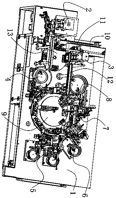
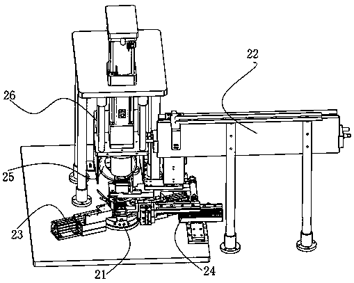
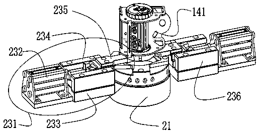
The invention relates to a device for automatically assembling a seat belt retractor. The device comprises a worktable; a first rotary disk device and a second rotary disk device that are arranged left and right are mounted at the upper part of the worktable; four placing stations are annularly arranged at the upper part of the first rotary disk device in an equally-spaced manner; a feeding manipulator, a ratchet assembling mechanism, a pressing mechanism and a transfer manipulator are sequentially mounted at the upper part of the worktable in the counterclockwise rotation direction o the first rotary disk device; a feeding conveying assembly is installed on the rear side of the feeding manipulator; eight assembling stations are annularly arranged at the upper part of the second rotary disk device in an equally-spaced manner; and an upper shell feeding mechanism, a mandrel main wheel feeding mechanism, a synchronous feeding mechanism, a first gear assembling mechanism, a second gear assembling mechanism, a third gear assembling mechanism and an end cover transfer press fitting mechanism are sequentially mounted at the upper part of the worktable in the rotation direction o the second rotary disk device; and the device has a compact structure, shortens the working process, fully automatically improves the assembling efficiency, reduces the manual participation, and improves theassembling accuracy and efficiency.

Description

technical field [0001] The invention relates to the technical field of retractor assembly equipment, in particular to an automatic assembly equipment for a safety belt retractor. Background technique [0002] At this stage, society is developing rapidly, people's living standards have been greatly improved, and people are paying more and more attention to the quality of life. Among them, cars are the most important means of transportation in life. The sales of cars are increasing, and the demand for their main parts is also increasing. ; Such as the retractor of the car seat belt, the function of the retractor is to store the webbing and lock the webbing to pull out, it is the most complicated mechanical part in the seat belt. There is a ratchet mechanism inside the retractor. Under normal circumstances, the occupant can pull the webbing freely and at a constant speed on the seat, but once the continuous pulling process of the webbing from the retractor stops or when the veh...

Claims


Application Information

Patent Timeline
Patent Type & Authority Applications(China)
IPC IPC(8): B23P21/00
CPCB23P19/001B23P19/007B23P21/006
Inventor 刘国红
Owner XUCHANG UNIV
Learn More