
Visual track inspection imaging system

An imaging system and track technology, which is used in measurement devices, material analysis by optical means, instruments, etc., can solve the problems of low power of imaging equipment, and achieve the effect of solving occlusion problems, reducing power requirements, and eliminating specular reflection interference.

Pending Publication Date: 2020-05-19
成都精工华耀科技有限公司
View PDF1 Cites 0 Cited by
  • Summary
  • Abstract
  • Description
  • Claims
  • Application Information

AI Technical Summary

Problems solved by technology

[0006] In order to solve the problem in the background technology that the rail head blocks the gauge baffle area and the mirror reflection on the rail surface cannot take into account the low power of the imaging equipment, the present invention provides a visual inspection imaging system for the rail, which can take into account the surface of the rail Dark-field lighting imaging of diseases and bright-field lighting imaging requirements for fasteners on both sides of the rail and ballast bed area, while effectively reducing power consumption and equipment size

Method used


Image

  • Visual track inspection imaging system
  • Visual track inspection imaging system
  • Visual track inspection imaging system

Examples


Embodiment 1

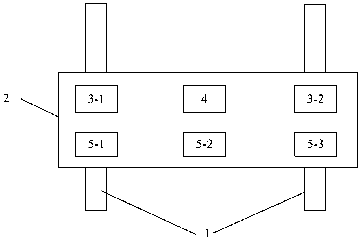
[0055] Such as figure 1 As shown, a track visual inspection imaging system, the system includes:

[0056] 1 2D imaging module A4, located directly above the center of the track bed;

[0057] Two 2D imaging modules B3-1, 3-2 are located directly above the center of the rails on both sides of the track, and are arranged in a line with the 2D imaging module A; and

[0058] Three 3D imaging modules 5-1, 5-2, 5-3, the three 3D imaging modules are located on the same plane and are respectively located directly above the center of the rail and directly above the center of the ballast bed on both sides of the track.

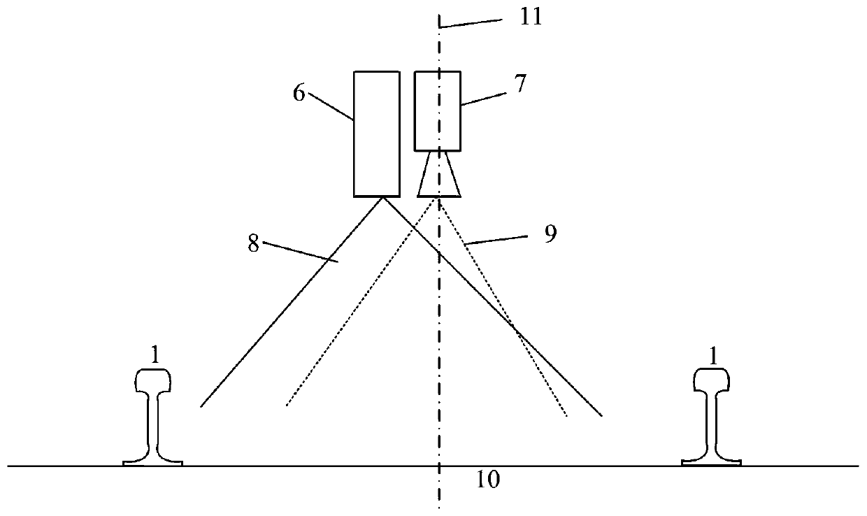
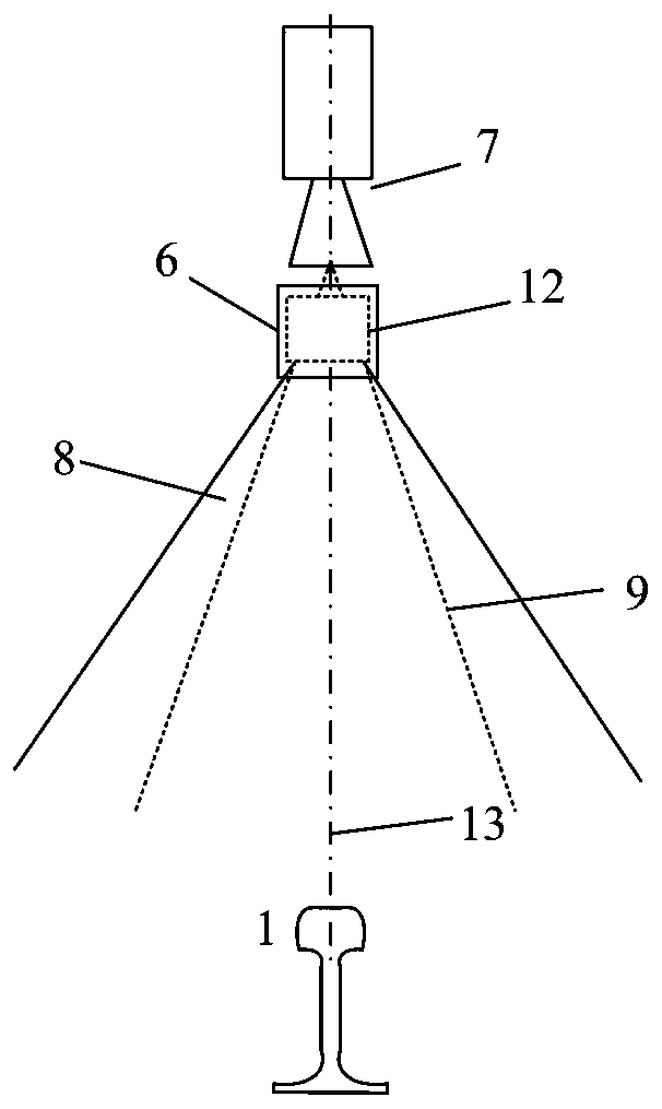
[0059] Such as figure 2 As shown, the 2D imaging module A is composed of a line structured light generator 6 and a line array camera 7; wherein the line structured light generator is a line laser, which produces a line structured light 8 with a thickness of 4mm, and the line array camera imaging plane 9 is aligned with the line structure The light 8 illuminates the p...

Embodiment 2

[0066] The difference from Embodiment 1 is that a line light source is added to perform dark-field lighting on the rail area to avoid specular reflection interference on the rail surface in Embodiment 1. In this embodiment, the line light source is an LED linear light source, and the irradiation area on the rail surface is 20*Umm.

[0067] Such as Figure 10 , 11 As shown, in the 2D imaging module B, a line light source 16 that illuminates obliquely downward is added to perform dark field illumination on the surface of the rail. At the same time, a width W The reflection mirror 15, the included angle between the reflection mirror 15 and the line-structured light plane is g, and g is not less than 5 degrees, and the reflection mirror obliquely reflects the line-structured light downward. The included angle between the illumination plane of the line light source 16 and the imaging plane of the line array camera is a, and the range of a is 60-90 degrees. Figure 12 It is a sch...

Embodiment 3

[0071] Compared with Embodiment 2, the line light source is an LED linear parallel light source, and the irradiation area on the rail surface is not less than 20*Umm.

[0072] The imaging system of this embodiment has a better dark field illumination effect after using parallel light sources.


PUM

PropertyMeasurementUnit
Thicknessaaaaaaaaaa

Abstract

The invention discloses a visual track inspection imaging system. The system is composed of a 2D imaging module A, two 2D imaging modules B and three 3D imaging modules, wherein the 2D imaging modulesB are respectively located right above the center of a steel rail, the 2D imaging modules A are located right above the center of a ballast bed, the three 2D imaging modules are arranged in a straight line to carry out two-dimensional scanning imaging on the surface of the whole rail, and the three 3D imaging modules are arranged in a straight line to carry out three-dimensional scanning imagingon the surface of the whole rail. According to the imaging system, two-dimensional and three-dimensional images of the surface of the rail can be obtained at the same time, the requirements for dark-field illumination imaging of rail surface diseases and bright-field illumination imaging of fasteners on the two sides of the rail and ballast bed areas are met, power consumption is effectively reduced, and the equipment size is reduced.

Description

technical field [0001] The invention relates to the technical field of rail disease patrol inspection, in particular to a visual rail inspection imaging system. Background technique [0002] Rail transit is the supporting industry of our transportation, and it plays great value in many aspects such as national economic development and people's daily life. As the infrastructure of rail transit, the performance status of rail is closely related to the safety of rail transit operation. After the subway has been in operation for a long time, due to various reasons such as train rolling, foundation settlement, and material aging, the track condition will gradually deteriorate, and various diseases such as gauge changes, rail fractures, and fastener failures will occur randomly. If it is not dealt with, it may lead to major traffic accidents such as train derailment. Therefore, track inspection and maintenance work is particularly important for subway safety operation management...

Claims


Application Information

Patent Timeline
IPC IPC(8): G01N21/95
CPCG01N21/8806G01N21/8851G01N21/95G01N2021/8809G01N2021/8822G01N2021/8887
Inventor 左丽玛
Owner 成都精工华耀科技有限公司
Learn More