
Integrated oil pumping device

An integrated, oil-pumping technology, used in rotary piston pumps, rotary piston/oscillating piston pump components, pumps, etc., can solve the problems of occupying transmission space, large flow leakage, and rapid kinetic energy drop, and achieves a reduction in Assembly space, small pressure pulsation, compact structure

Pending Publication Date: 2020-05-19
重庆红宇精密工业集团有限公司
View PDF0 Cites 0 Cited by
  • Summary
  • Abstract
  • Description
  • Claims
  • Application Information

AI Technical Summary

Problems solved by technology

[0003] This kind of oil pumping device has a single structure, long oil circuit, large flow leakage, rapid kinetic energy drop, high energy consumption, and it is easy to cause pressure pulsation in the transmission system to affect the performance of the transmission; not only that, the oil pumping device, gear shifting The mechanism and other actuators are configured independently, occupying a large amount of space in the transmission, which is not conducive to the development trend of compact, intelligent and lightweight transmissions
[0004] Due to the above shortcomings, the oil pumping device of the traditional automatic transmission is limited in the application of more and more attention to efficiency and intelligent component integration

Method used


Image

  • Integrated oil pumping device
  • Integrated oil pumping device
  • Integrated oil pumping device

Examples


Embodiment 1

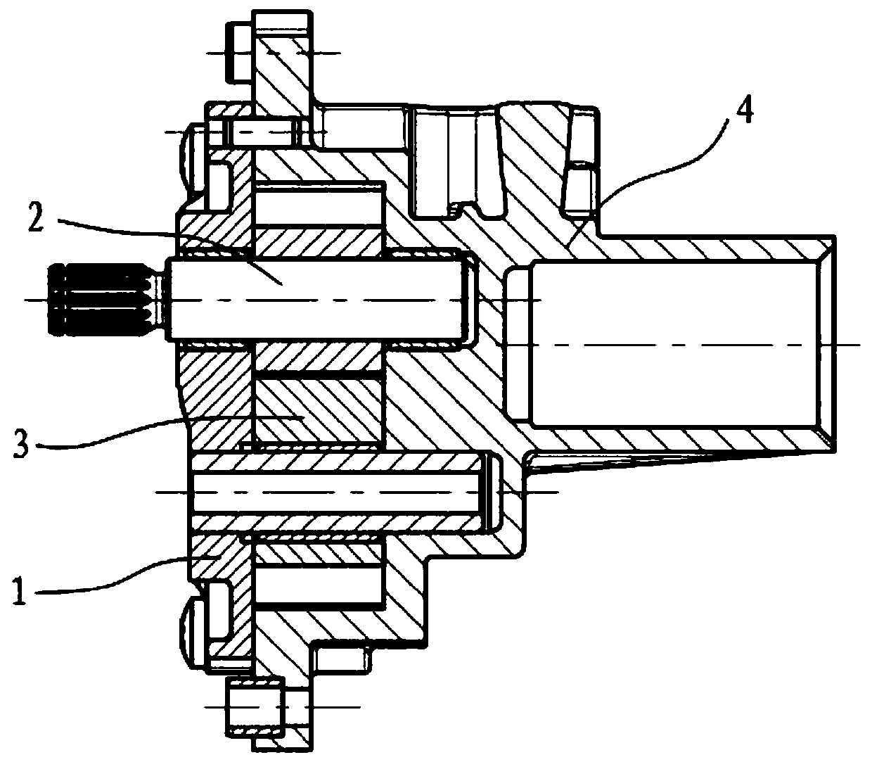
[0046] This embodiment discloses an integrated oil pumping device, see figure 1 , including a pump cover assembly 1 , a drive assembly 2 , a driven assembly 3 and a pump body assembly 4 .

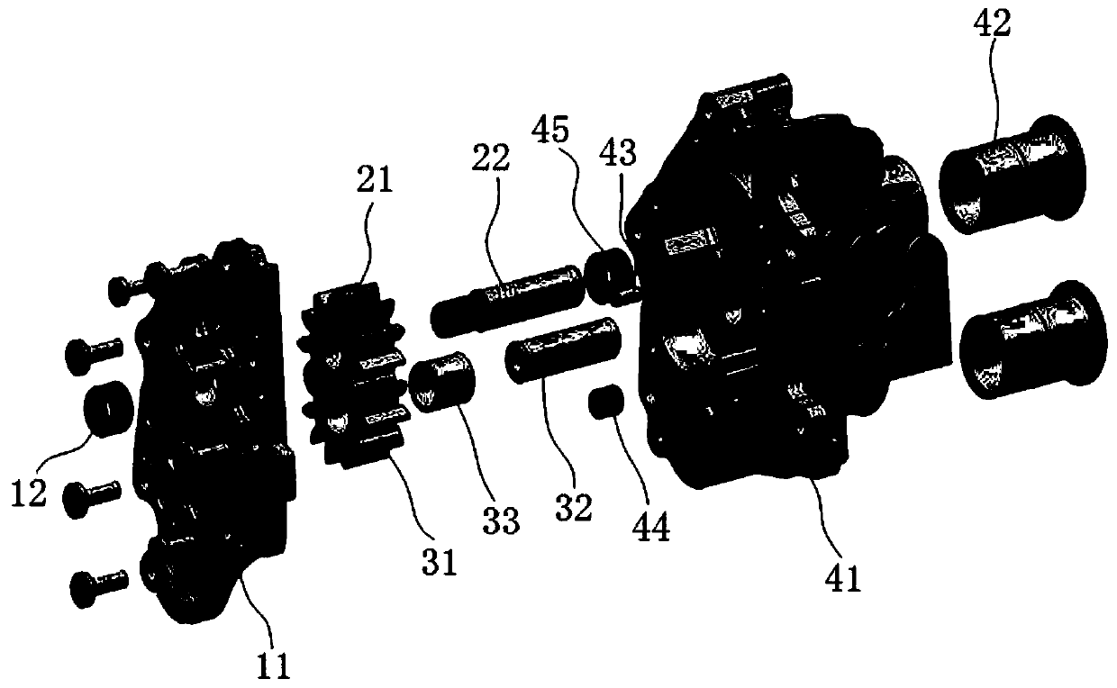
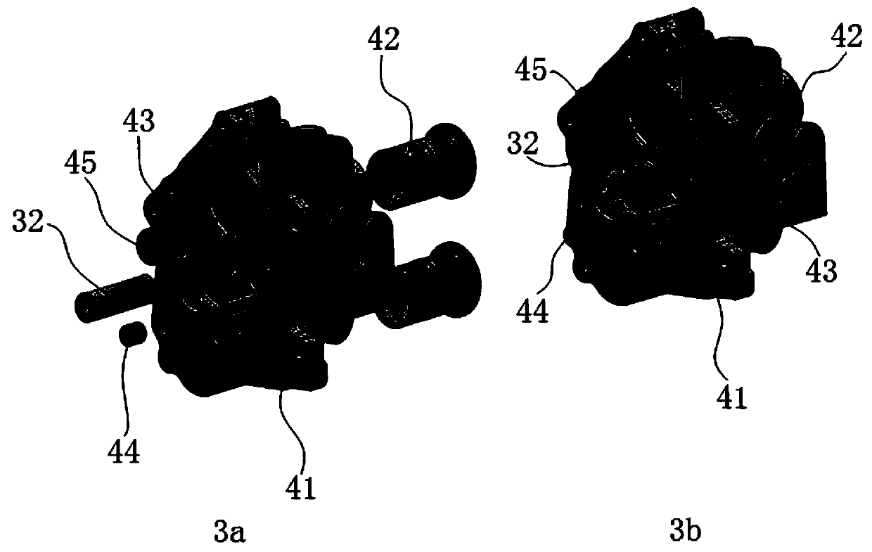
[0047] see Figure 2 to Figure 5 , the main component of the pump body assembly 4 is the pump body 41 .

[0048] A pair of gear cavities are processed in the middle of the pump body 41, and the drive shaft shaft hole I4101 and the driven shaft shaft hole I4102 are respectively processed in the gear cavity. An oil drain groove 41011 is opened at the bottom of the shaft hole I4101 of the drive shaft. The shaft hole I411 of the drive shaft is press-fitted with a pump body bushing 45 through interference fit, and the pump body bushing 45 is a bimetal rolled bush.

[0049]An oil inlet groove I4103 and an oil outlet groove I4104 are respectively provided at the upper and lower ends of the gear chamber. The oil outlet groove I4104 is connected to the shaft hole I4102 of the driven shaft throug...

Embodiment 2

[0066] This embodiment discloses a relatively basic implementation method, an integrated oil pumping device, see figure 1 , including a pump cover assembly 1 , a drive assembly 2 , a driven assembly 3 and a pump body assembly 4 .

[0067] see Figure 2 to Figure 5 , the main component of the pump body assembly 4 is the pump body 41 .

[0068] A pair of gear cavities are processed in the middle of the pump body 41, and the drive shaft shaft hole I4101 and the driven shaft shaft hole I4102 are respectively processed in the gear cavity.

[0069] An oil inlet groove I4103 and an oil outlet groove I4104 are respectively provided at the upper and lower ends of the gear chamber.

[0070] The side wall of the pump body 41 is provided with an oil inlet 4107 connected to the oil inlet groove I4103 and an oil return port 4109. The oil return port 4109 is used to collect the oil return of the transmission hydraulic system. The oil return has a certain pressure and is It communicates wi...

Embodiment 3

[0083] The main structure of this embodiment is the same as that of Embodiment 2. Furthermore, a buffer groove I1107 extends on the side wall of the oil outlet groove II1104 close to the shaft hole II1101 of the drive shaft. A buffer groove II1108 extends on the side wall of the oil outlet groove II1104 close to the shaft hole II1102 of the driven shaft.


PUM

PropertyMeasurementUnit
Groove depthaaaaaaaaaa

Abstract

The invention discloses an integrated oil pumping device. The integrated oil pumping device comprises a pump cover assembly, a driving assembly, a driven assembly and a pump body assembly; the main component of the pump body assembly is a pump body; a pair of gear cavities are formed in the centre of the pump body; an oil inlet groove I and an oil outlet groove I are respectively formed in the upper end and the lower end of each gear cavity; the driving assembly comprises a driving gear and a driving shaft; the driven assembly comprises a driven gear and a driven shaft; the driving gear and the driven gear are positioned in the gear cavities and are engaged with each other; the main component of the pump cover assembly is a pump cover; and the pump cover is mounted on the pump body. The integrated oil pumping device disclosed by the invention is short in oil way, low in leakage, low in energy consumption, low in pressure pulsation and compact in structure, greatly reduces the assembling space, and has a prospective technical effect.

Description

technical field [0001] The invention belongs to the technical field of automatic transmissions of automobiles, and in particular relates to an integrated oil pumping device. Background technique [0002] Traditional automotive automatic transmissions use an independent pumping device to provide power for the hydraulic transmission system. Whether it is an automatic transmission that uses a cycloid rotor pump or a gear pump, it controls each shifting mechanism and actuator through valve plate oil distribution. [0003] This kind of oil pumping device has a single structure, long oil circuit, large flow leakage, rapid kinetic energy drop, high energy consumption, and it is easy to cause pressure pulsation in the transmission system to affect the performance of the transmission; not only that, the oil pumping device, gear shifting The mechanism and other actuators are configured independently, occupying a large amount of space in the transmission, which is not conducive to the ...

Claims


Application Information

Patent Timeline
IPC IPC(8): F04C2/18F04C15/06F04C15/00
CPCF04C2/18F04C15/00F04C15/0088F04C15/064
Inventor 杨昌林张德键申小刚
Owner 重庆红宇精密工业集团有限公司
Learn More