
High efficiency high-pressure sensor testing machine

A high-pressure sensor and testing machine technology, applied in instruments, measuring fluid pressure, measuring devices, etc., can solve the problems of complex detection steps, high detection costs, low accuracy, etc., and achieve perfect alarm function, high accuracy, and safety. high effect

Inactive Publication Date: 2010-02-10
SHENYANG ACAD OF INSTR SCI
View PDF6 Cites 0 Cited by
  • Summary
  • Abstract
  • Description
  • Claims
  • Application Information

AI Technical Summary

Problems solved by technology

[0002] At present, the existing sensor-specific detection equipment can realize sine wave servo control, and its shortcoming is mainly that it is a single waveform
However, the existing sensor-specific detection combination equipment can realize quasi-sine wave servo control. The main disadvantage is that it is a quasi-sine wave. The combination device is a combination of multiple devices, and the equipment is complicated.
Recently, relevant foreign materials have reported that there is a special device that can realize servo control of various waveforms, but the detection steps are complicated, the equipment is expensive, and the detection cost is high.
In summary, the existing sensor-specific detection equipment is characterized by: it is used in pressure screening equipment, the accuracy is not high, the waveform is single (quasi-sine wave), and the frequency is low

Method used


Image

  • High efficiency high-pressure sensor testing machine
  • High efficiency high-pressure sensor testing machine
  • High efficiency high-pressure sensor testing machine

Examples


example 1

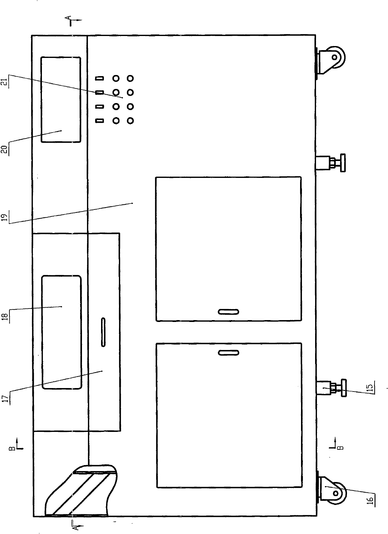
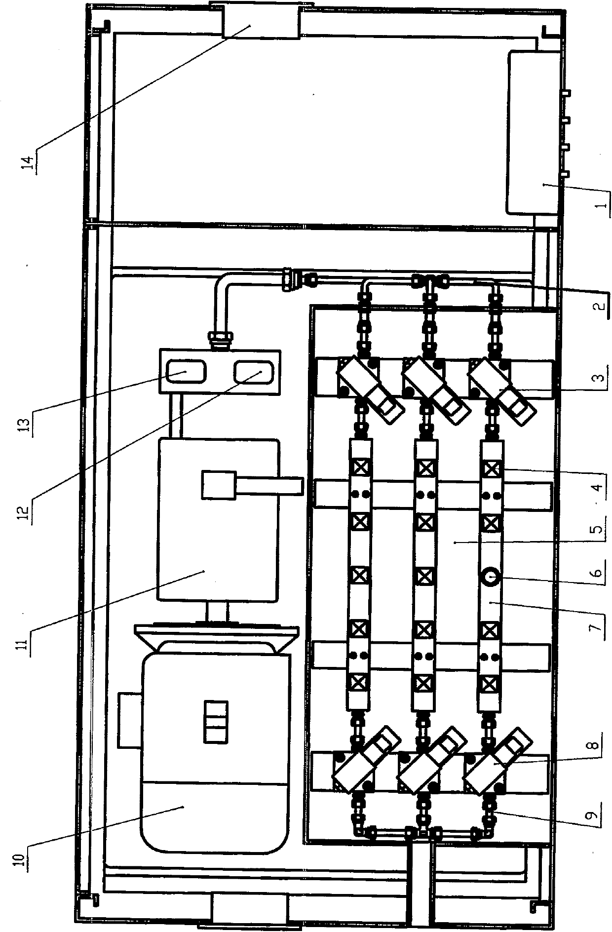
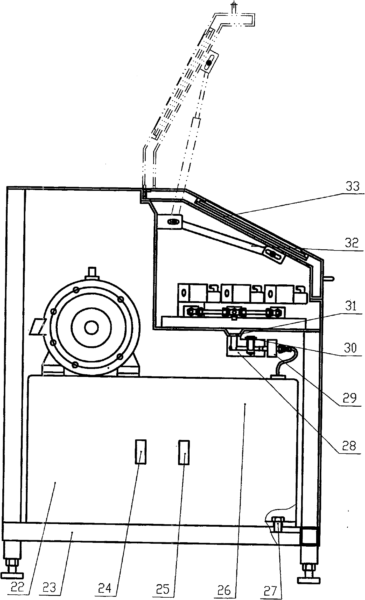
[0027] Such as Figure 1~3 As shown, the complete machine is supported by four shock-absorbing adjustment pad irons 15 below the base plate 23, and four casters 16 are set simultaneously to facilitate movement. The cabinet 19 and the pressure generating system 26 are connected on the bottom plate 23 .

[0028] The pressure generating system 26 is mainly composed of a fuel tank 22, a motor 10, a variable pump 11, a servo relief valve 12, an electromagnetic pressure regulating valve 13, a liquid level sensor 24, a temperature sensor 25, etc., which are fixed on the base plate 23 by a positioning device 27. The variable displacement pump 11 is connected to the motor 10 , and its pressure outlet is connected to the pipeline 2 through the electromagnetic pressure regulating valve 13 and the servo overflow valve 12 . After the pipeline 2 is connected in parallel to three routes, it leads to the test area 5 which can be kept closed, and is connected to the installation fixture 7 thr...


PUM


Abstract

A high-efficiency high-pressure sensor testing machine comprises a bottom plate provided with a truckle, which has the technical point that: a cabinet and a pressure generating system is connected onthe bottom plate, wherein the system comprises an oil tank fixedly arranged on the bottom plate, a motor and a variable pump are sequentially arranged on the upper part of the oil tank, the pressure outlet of the system is connected with a pipeline through an electromagnetic pressure regulator and a servo overflow valve, after being paralleled to be three-way, the pipeline is led to a testing areawhich is kept closed; an installation clamp is arranged in the testing area through conversion connection of a nested connector, each installation clamp is provided with two to eight installation positions, each of which is provided with a standard pressure sensor and a plurality of tested pressure sensor; a pressurized valve is serially connected to a pressure inlet end of the installation clamp, a cutoff valve is serially connected to a pressure outlet end of the installation clamp, and three-way pressure pipelines are paralleled to one way after the cutoff valve, and connected to a leakagedischarge outlet at the lower part of the testing area; a panel computer and an electrical operation area are embedded into the upper part of the cabinet.

Description

technical field [0001] The invention belongs to the technical field of measuring physical parameters of products, in particular to a high-efficiency high-voltage sensor testing machine for performance testing of sensors. Background technique [0002] At present, the existing sensor-specific detection equipment can realize sine wave servo control, and its shortcoming is mainly a single waveform. However, the existing combined equipment for sensor-specific detection can realize quasi-sine wave servo control. The main disadvantage is that it is a quasi-sine wave, and the combination device is a combination of multiple devices, and the equipment is complicated. Recently foreign relevant materials report that there is a special device that can realize the servo control of multiple waveforms, but the detection steps are complicated, the equipment is expensive, and the detection cost is high. To sum up, the existing sensor-specific detection equipment is characterized by: it is us...

Claims


Application Information

Patent Timeline
Patent Type & Authority Patents(China)
IPC IPC(8): G01L27/00
Inventor 李延夫吴虹苑庆迪于振毅刘殿东杜健
Owner SHENYANG ACAD OF INSTR SCI
Learn More