
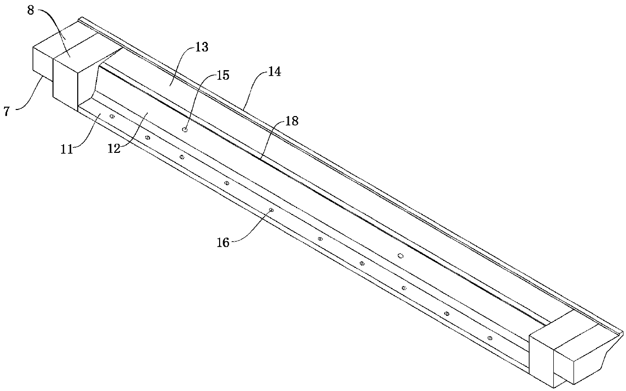
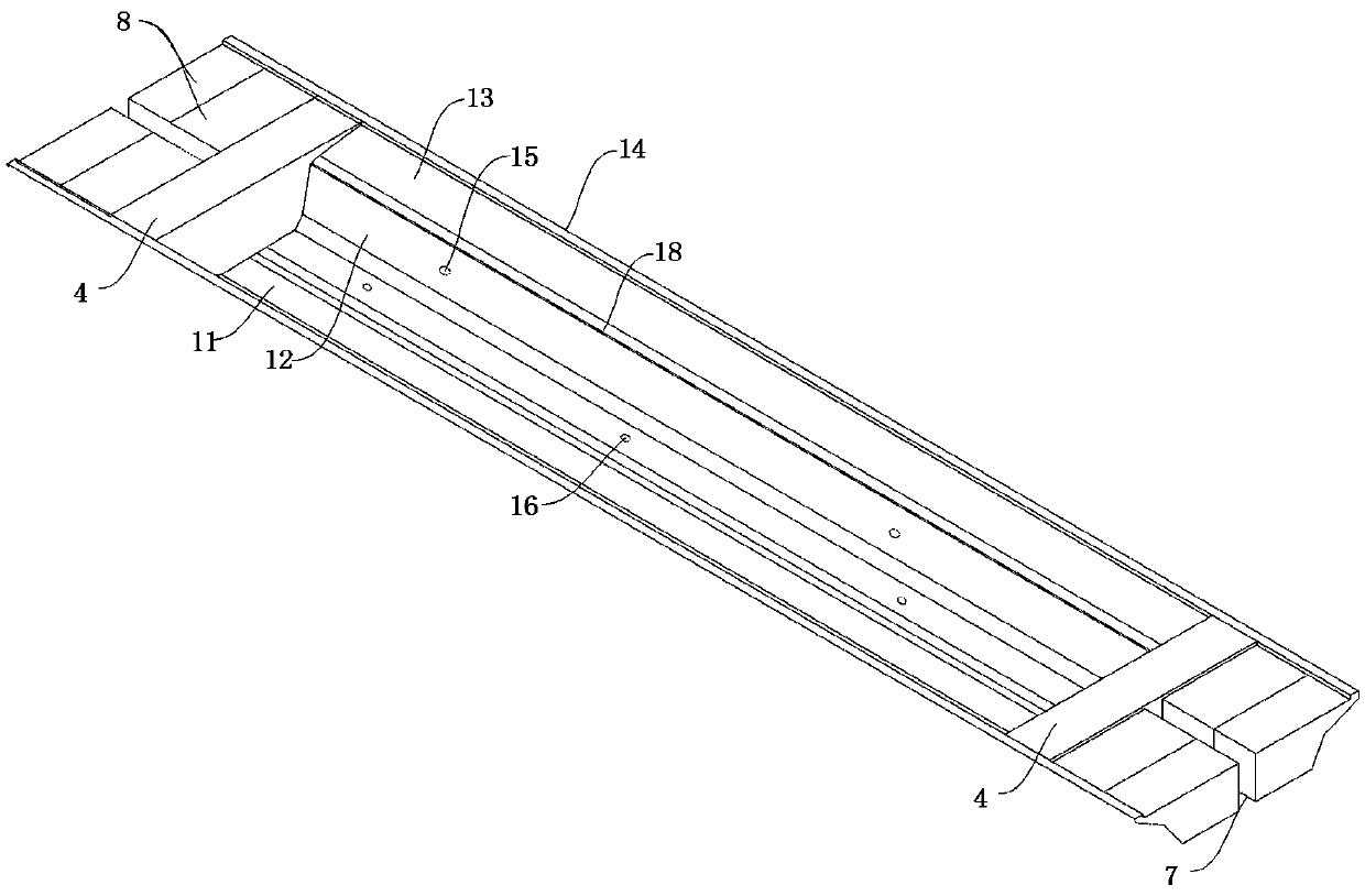
Half-through type longitudinal partitioning prefabricated box girder

A longitudinal beam and block technology, used in bridges, bridge parts, bridge materials, etc., can solve the problems of difficult construction of prefabricated beam fields, large impact on municipal roads, and difficulty in adopting

Pending Publication Date: 2020-05-19
JIESHUN RAIL TRAFFIC TECH CHONGQING +1
View PDF0 Cites 0 Cited by
  • Summary
  • Abstract
  • Description
  • Claims
  • Application Information

AI Technical Summary

Problems solved by technology

[0003] However, the existing prefabricated box girder needs a large-scale bridge erecting machine to erect during construction. Considering the turnover rate of the bridge erecting machine equipment, it is usually required that the viaduct bridge should be continuous for more than 10 kilometers. For areas with complex terrain and inconvenient transportation , prefabricated box girder transportation is inconvenient, and prefabricated girder field is not easy to build, such as hilly and mountainous urban areas, it is difficult to adopt traditional prefabricated box girder technology for short-length elevated section box girders, intelligently adopts cast-in-place technology, and each span box girder site The operation time takes about 2 months, which has a great impact on municipal roads and a long construction period

Method used


Image

  • Half-through type longitudinal partitioning prefabricated box girder
  • Half-through type longitudinal partitioning prefabricated box girder
  • Half-through type longitudinal partitioning prefabricated box girder

Examples


Embodiment Construction

[0024] In order to make the purpose, technical solutions and advantages of the embodiments of the present invention clearer, the technical solutions in the embodiments of the present invention will be clearly and completely described below in conjunction with the accompanying drawings in the embodiments of the present invention. Obviously, the described embodiments It is some embodiments of the present invention, but not all of them. The components of the embodiments of the invention generally described and illustrated in the figures herein may be arranged and designed in a variety of different configurations.

[0025] Accordingly, the following detailed description of the embodiments of the invention provided in the accompanying drawings is not intended to limit the scope of the claimed invention, but merely represents selected embodiments of the invention. Based on the implementation manners in the present invention, all other implementation manners obtained by persons of or...


PUM


Abstract

The invention discloses a half-through type longitudinal partitioning prefabricated box girder. The Z-shaped longitudinal beam A and the Z-shaped longitudinal beam B are oppositely arranged; sedimentation steps are arranged at the two ends of the Z-shaped longitudinal beam A and the Z-shaped longitudinal beam B; the two ends of the Z-shaped longitudinal beam A and the two ends of the Z-shaped longitudinal beam B are connected through end cross beams. The bottoms of the Z-shaped longitudinal beam A and the Z-shaped longitudinal beam B located between the cross beams at the two ends are connected through a bottom plate wet joint, the composite slabs are mutually assembled on steps on the upper portions of the Z-shaped longitudinal beam A and the Z-shaped longitudinal beam B, and the top plate post-pouring layer is poured on an upper cavity formed by the Z-shaped longitudinal beam A, the Z-shaped longitudinal beam B and the composite slabs. The beneficial effects of the invention are that: the method is suitable for large-scale production; implementing factory batch prefabrication, according to the method, the construction cost is reduced, a small part of operation sites are manufactured, the construction efficiency is improved, the labor environment of workers is improved, the influence on municipal road traffic interference and urban environment dust and noise pollution is reduced, the requirement for transportation and installation equipment is low, the requirement for site conditions and line conditions is low, and therefore the method can be flexibly applied to an urban elevated section structure.

Description

technical field [0001] The invention relates to the technical field of box girder erection, in particular to a center-supported longitudinal block prefabricated box girder. Background technique [0002] Box girders are divided into prefabricated box girders and cast-in-place box girders. The prefabricated box girder can be prefabricated by the whole hole or the transverse section. After the substructure is completed, large-scale transportation equipment and bridge erection frames are used to erect or splice on site. The construction progress is fast and the on-site operation time is short, but the turnover of bridge erecting machine equipment should be considered. rate, it is usually required that the viaduct must be continuous for more than 10 kilometers. The cast-in-place box girder can be completed by moving the sliding form or erecting full-scale brackets on site. All the work is completed on site, and the on-site operation takes a long time, especially the full-scale b...

Claims


Application Information

Patent Timeline
Patent Type & Authority Applications(China)
IPC IPC(8): E01D2/04E01D19/06E01D21/00E01D101/24
CPCE01D2/04E01D19/067E01D21/00E01D2101/24
Inventor 赵晓波吴天李秀江韦登厚李燕清万静潘莉卓杨旭
Owner JIESHUN RAIL TRAFFIC TECH CHONGQING
Learn More