
Surveillance device for cable transport apparatus and surveillance method

A technology for controlling devices and conveying equipment, applied in cable railways, transportation and packaging, climate sustainability, etc., can solve the problems of increasing equipment costs and burdens, and achieve the effect of good device availability and good device reliability.

Active Publication Date: 2012-07-11
宝玛佳奇
View PDF8 Cites 0 Cited by
  • Summary
  • Abstract
  • Description
  • Claims
  • Application Information

AI Technical Summary

Problems solved by technology

[0005] However, doubling the breaking prongs also doubles the safety wires, which greatly increases the cost of the device and its burden

Method used


Image

  • Surveillance device for cable transport apparatus and surveillance method
  • Surveillance device for cable transport apparatus and surveillance method
  • Surveillance device for cable transport apparatus and surveillance method

Examples


Embodiment Construction

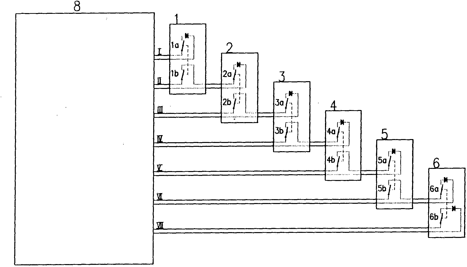
[0063] figure 1 It schematically shows the control device according to the embodiment of the present invention in the case of N=6 (ie, in the case of 6 components to be monitored distributed in the whole space, here 6 towers). Undoubtedly, the invention applies to any number of components with N>2 to be monitored, the case of N<2 providing only little practical significance. Then, the towers are sequentially numbered in such a way that tower n is physically positioned between tower n-1 and tower n+1, with 1<n<N-1.

[0064] The towers 1, 2, 3, 4, 5, 6 carry aerial cables not shown in the figure. The control device according to the invention comprises 12 switches, 1a, 1b to 6a, 6b, two of which are arranged on each tower in such a way that the switch opens if the cable derails.

[0065] The control device further comprises a safety electrical cabinet 8, to which the 12 switches 1a to 6b are connected by 7 wires in the following manner:

[0066] - the first switch 1a of the fi...


PUM


Abstract

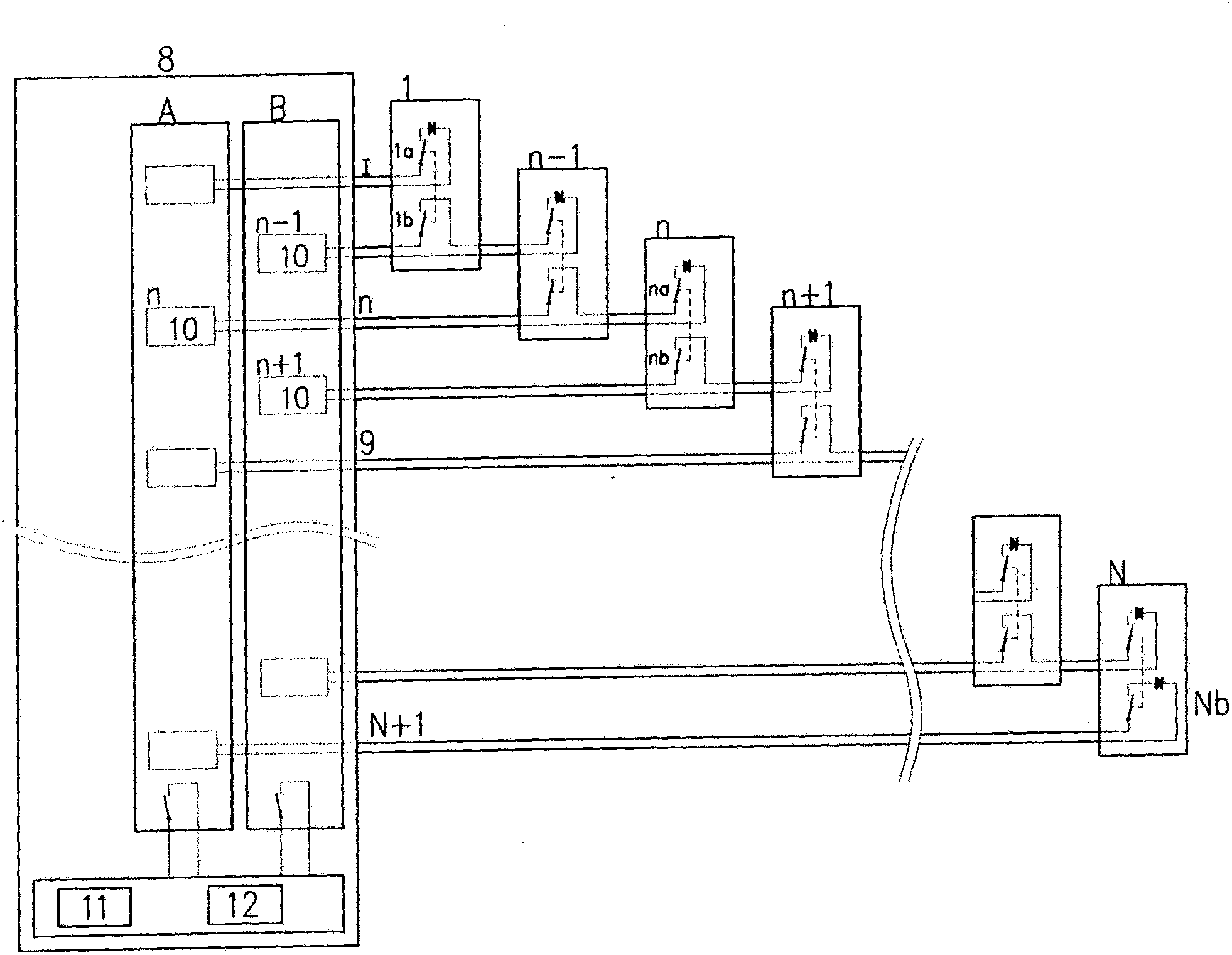
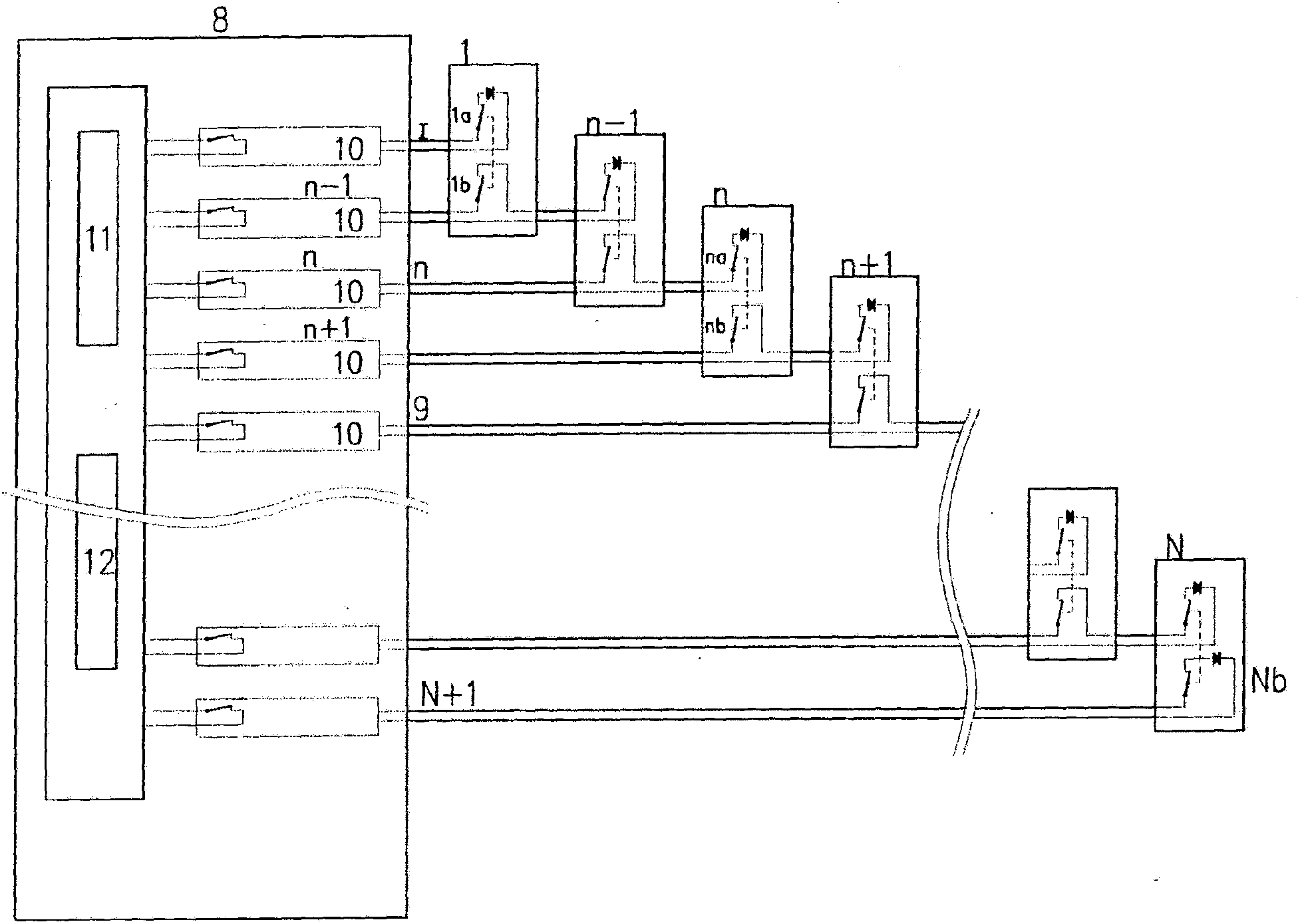
The invention relates to a surveillance device for a transport apparatus that comprises a cable carried by N pylons (1-6), characterized in that the surveillance device comprises: at least 2N switches (1a-6b), two switches being provided at each pylon; a safety electric cabinet (8); N+1 electric lines (I-VII) connecting the switches to the safety electric cabinet, the switches being laid in the following manner: a first electric line connects one of the switches of the first pylon to the electric safety cabinet; a N+1st electric line connects one of the switches of the Nth pylon to the safety electric cabinet; the same electric line n connects in series, for any integer n between 2 and N, one of the switches of the pylon n-1 and one of the switches of the pylon n to the safety electric cabinet.

Description

technical field [0001] The invention relates to a control device for cable transmission equipment, in particular to a control device and a control method for high-altitude cable transmission equipment. Background technique [0002] In conveying or traction equipment, especially in pods, cranes, chair lifts and similar equipment, it is absolutely necessary to stop the equipment instantaneously in the event of cable derailment (derailment). For this purpose, it is known, for example in FR2548612, to connect the conveying equipment with one or several safety wires, the interruption of which, especially during cable derailment, stops the equipment. In FR2548612 the security line comprises a conductive break fork which is arranged near a guide sheave and which can be broken by the lowering of the cable. Therefore, the falling (falling) of the cable interrupts the safety thread. [0003] However, these conveying devices, often located in high mountains, are often exposed to extr...

Claims


Application Information

Patent Timeline
Patent Type & Authority Applications(China)
IPC IPC(8): B61B12/06
CPCB61B12/06Y02T30/30Y02T30/00
Inventor 卢卡·马尔纳斯埃里克·博盖佩西
Owner 宝玛佳奇
Learn More