
Bridge erecting machine for small-curve railway box girder

A small curve, bridge erecting machine technology, applied in bridges, bridge construction, erection/assembly of bridges, etc., can solve the problems that cannot meet the requirements of small curve railway box girder erection

Active Publication Date: 2012-05-09
QINHUANGDAO TIANYE TOLIAN HEAVY INDUSTRY CO LTD +1
View PDF0 Cites 0 Cited by
  • Summary
  • Abstract
  • Description
  • Claims
  • Application Information

AI Technical Summary

Problems solved by technology

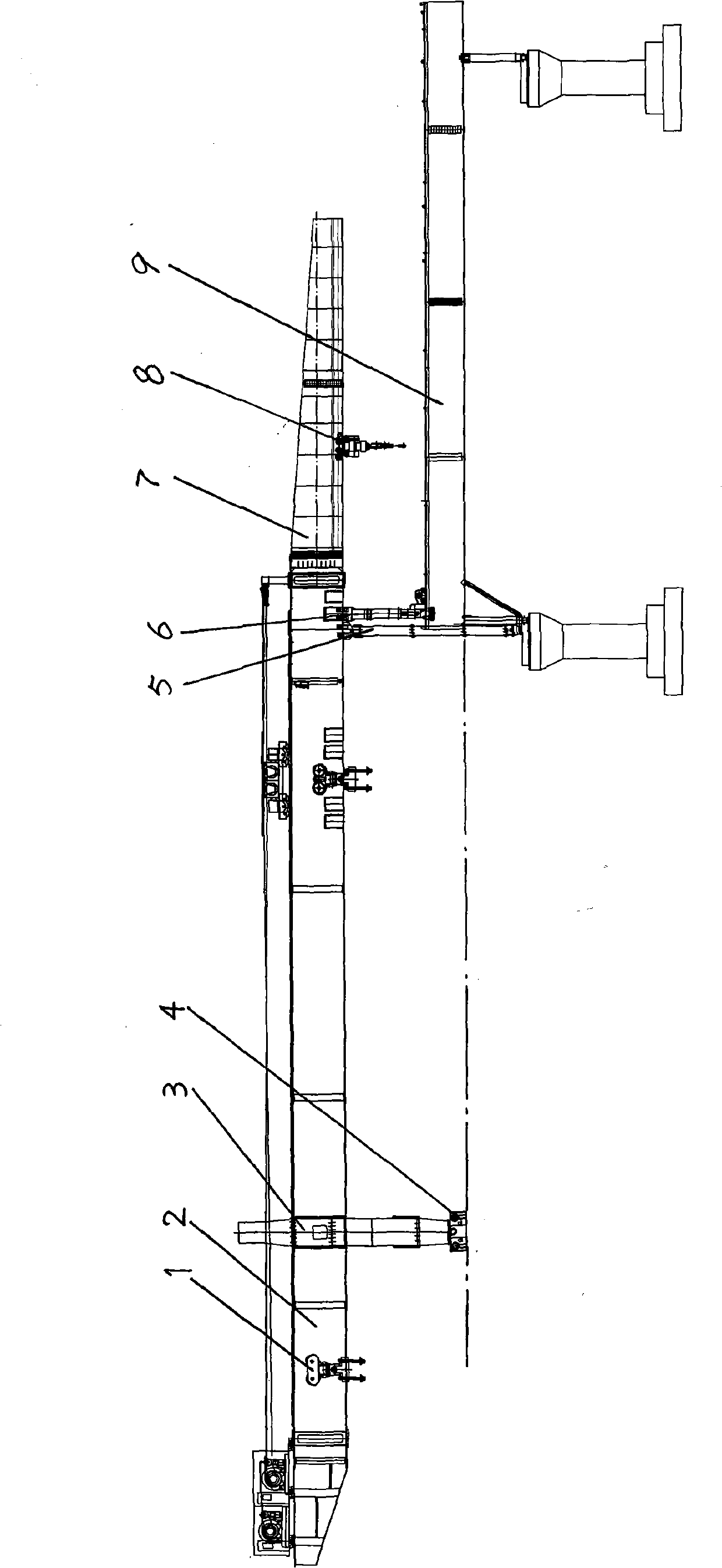
[0004] In order to solve the problem that the existing bridge erecting machine cannot meet the requirements for erecting small curved railway box girders, the present invention provides a small curved railway box girder bridge erecting machine, which can realize the erection of small curved box girders with a radius of curvature up to 500 meters

Method used


Image

  • Bridge erecting machine for small-curve railway box girder
  • Bridge erecting machine for small-curve railway box girder
  • Bridge erecting machine for small-curve railway box girder

Examples


Embodiment 1

[0023] Embodiment 1: If erecting the R1200 meter curve radius bridge calculation on the spot: the distance S=21m between the dolly lifting point and the center of rotation, the lateral displacement δ of the dolly is ± 0.57m, and the width of the laterally moving rail frame is at least 4.5m (structure control).

[0024] The left running speed of the rear outrigger is 2.98m / min, and the right running speed of the rear outrigger is 3m / min. Just adjust the output frequency of the left frequency converter 1UA of the rear outrigger to 49.8HZ, and the output frequency of the right frequency converter 1UB of the rear outrigger Adjust the frequency to 50HZ to realize the differential operation of the rear outriggers and complete the curve erection of the bridge machine.

Embodiment 2

[0025] Embodiment 2: If erecting 500 meters of curved radius bridges on the spot, calculate: the distance S=21m between the lifting point of the trolley and the center of rotation, the lateral movement δ of the trolley is ±1.37m, and the width of the laterally moving rail frame is at least 6m.

[0026] The left running speed of the rear outrigger is 2.96m / min, and the right running speed of the rear outrigger is 3m / min. Just adjust the output frequency of the left inverter 1UA of the rear outrigger to 49.4HZ, and the output frequency of the right inverter 1UB of the rear outrigger Adjust the frequency to 50HZ to realize the differential operation of the rear outriggers and complete the curve erection of the bridge machine.


PUM


Abstract

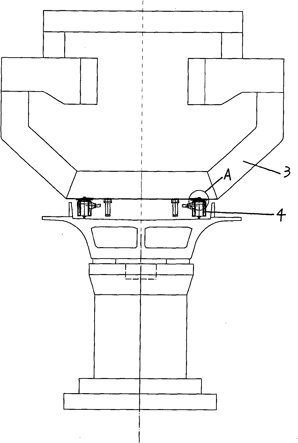
The invention belongs to erecting equipment for railway box girders, and in particular relates to a bridge erecting machine for a small-curve railway box girder, which solves the problem that the conventional bridge erecting machine cannot meet the requirement of the erection of the small-curve railway box girder. The bridge erecting machine for the small-curve railway box girder comprises a box-shaped girder which is arranged on a front outrigger, an auxiliary outrigger and a back outrigger, wherein the bottom of the back outrigger supports on back outrigger trolleys; the fronting end of the box-shaped girder is connected with a cantilever beam; both sides of the width of the cantilever beam are provided with longitudinal overhead rails; a cantilever crane is arranged on the longitudinal overhead rails; the cantilever crane comprises a longitudinal movement mechanism and a horizontal movement mechanism; the horizontal movement mechanism comprises a horizontal movement rail frame; a bogie is arranged on the horizontal movement rail frame, and the horizontal movement quantity of the bogie is delta= SL / R; the back outrigger and the auxiliary outrigger are provided with a vertical hinge mechanism; and the two back outrigger trolleys are provided with differential mechanisms. The bridge erecting machine has the advantage that a wide structure of the horizontal movement mechanism of the cantilever beam is matched with the vertical hinge mechanism of the back outrigger and the auxiliary outrigger and the differential mechanisms of the two back outrigger trolleys to realize the erection of the small-curve box girder with a 500-meter curvature radius.

Description

technical field [0001] The invention belongs to railway box girder erecting equipment, in particular to a small curved railway box girder bridge erecting machine, which can realize the erection of small curved box girders with a curvature radius of up to 500 meters. Background technique [0002] At present, in the design of foreign high-speed railways, in order to ensure the safety of high-speed traffic, the radius of curvature of the line is generally more than 2000m. However, there are a large number of small curved bridges in the design of domestic intercity railways. For example, there are prefabricated beams with a radius of curvature of 500m in Haikou City on the East Ring Railway in Hainan, and prefabricated beams with a radius of curvature of 600m in the intercity railway from Chengdu to Dujiangyan. [0003] Existing bridge erecting machines usually include a box-shaped main girder installed on the rear outrigger and front outrigger with a trolley; Hanging beam cran...

Claims


Application Information

Patent Timeline
Patent Type & Authority Patents(China)
IPC IPC(8): E01D21/10
Inventor 王金祥李慧敏王书新魏福祥覃艳明文珂刘宝庆杨保升王宏敏刘会平李坤田朝霞赵瑞轩吴永奋李晓东李伟葛强李全姚帆温志田
Owner QINHUANGDAO TIANYE TOLIAN HEAVY INDUSTRY CO LTD
Learn More