Heat conduction device
A technology of heat conduction and devices, applied in the field of heat conduction, can solve the problems of low heat dissipation efficiency and unsatisfactory heat dissipation effect of heat sinks, achieve good heat dissipation effect, small cavity volume, and overcome low heat transfer density
- Summary
- Abstract
- Description
- Claims
- Application Information
AI Technical Summary
Problems solved by technology
Method used
Image

Examples
Embodiment 1
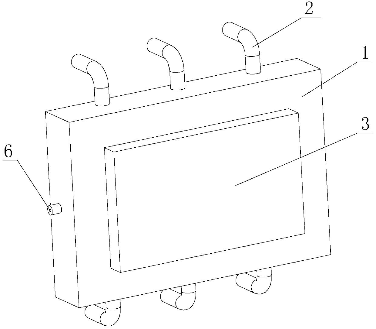
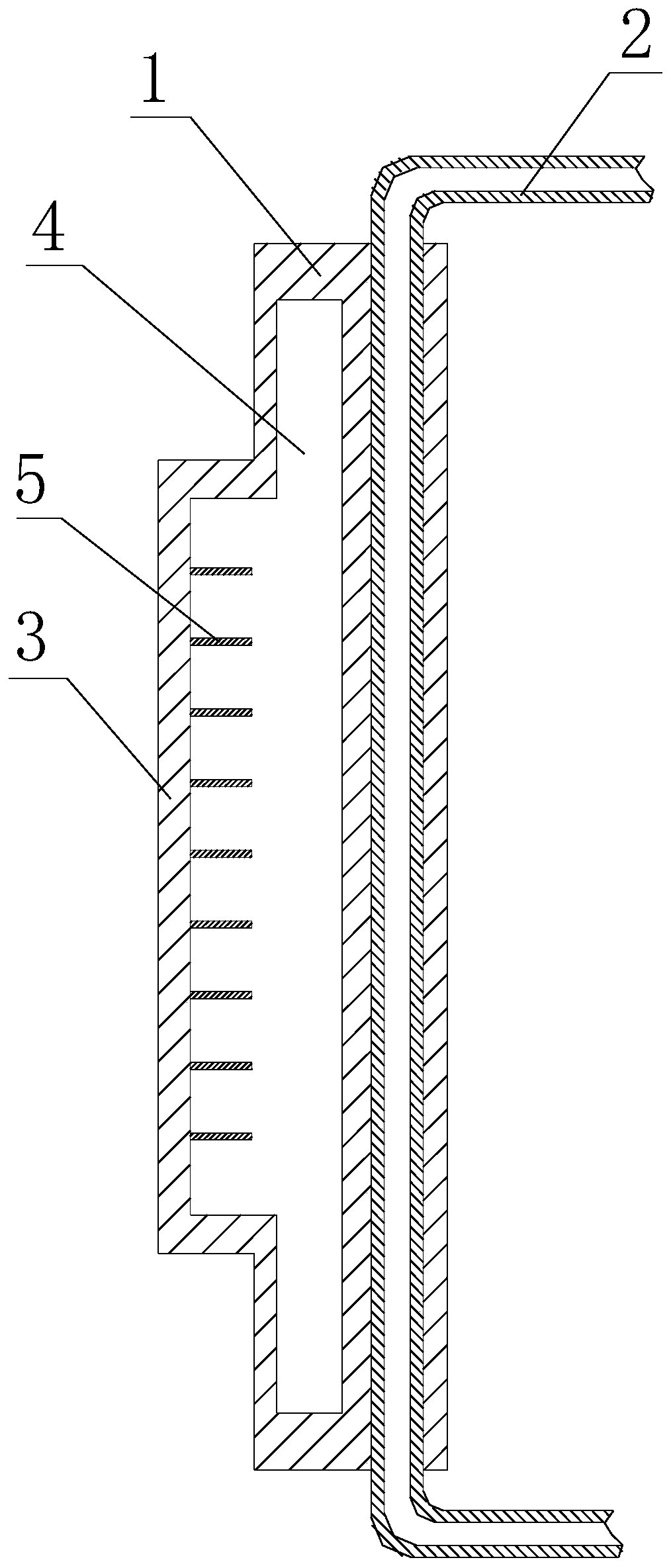
[0028] Such as Figure 1 to Figure 5 As shown, a heat conduction device includes a heat conduction block 1 and a heat pipe 2 . One side of the heat conduction block 1 is provided with a heat transfer boss 3 . A cavity 4 is arranged inside the heat conduction block 1 . The cavity 4 is filled with working fluid. Several heat exchange fins 5 are arranged on the inner wall of the cavity 4 near the heat transfer boss 3 . The heat exchange fins 5 are made of aluminum. The heat pipe 2 passes through the heat conduction block 1 . A section of the heat pipe 2 passing through the heat conduction block 1 is close to the cavity 4 .
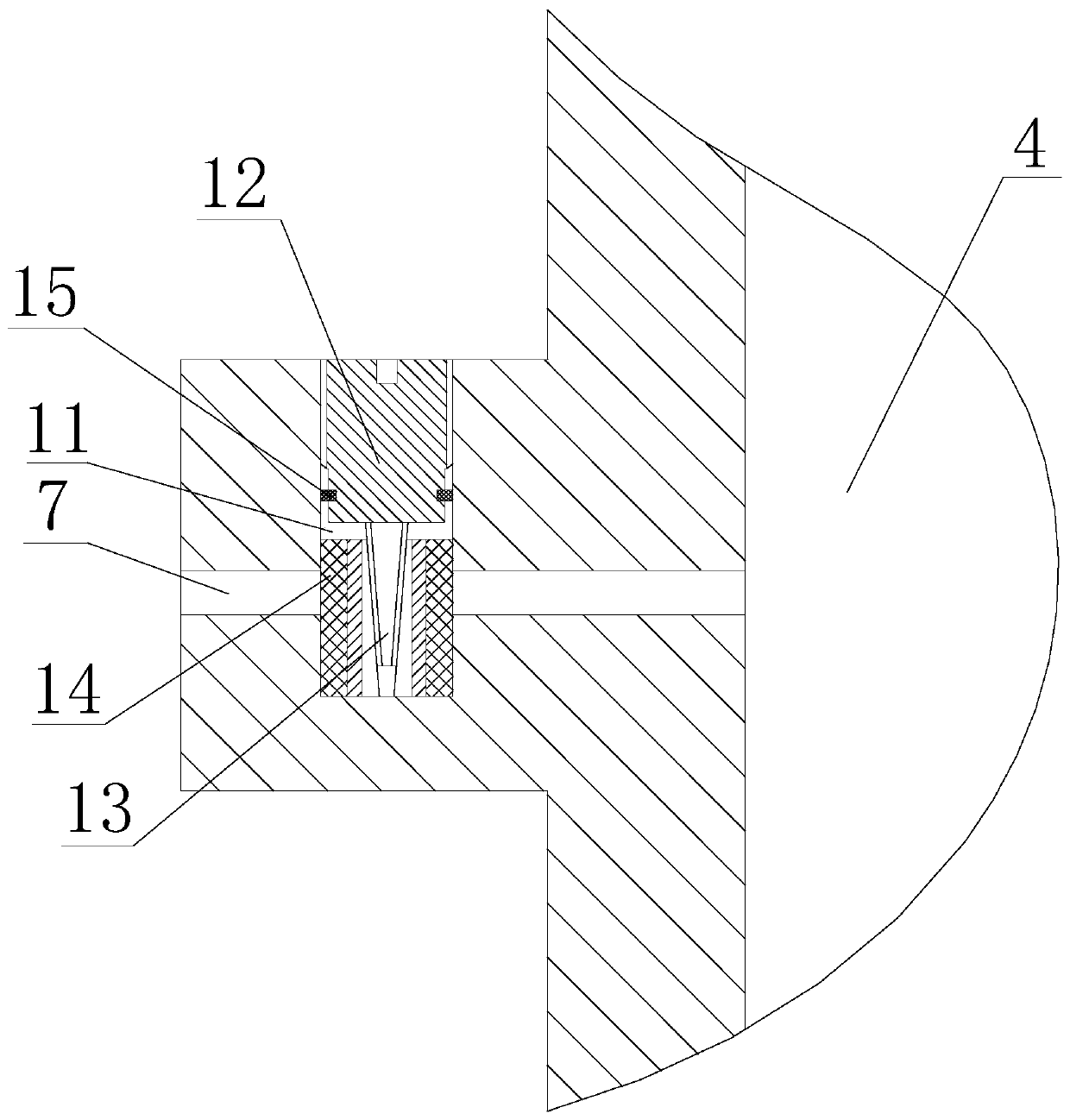
[0029] The heat conduction block 1 is provided with a filling port 6 . The filling port 6 includes a first filling channel 7 arranged on the heat conduction block 1 . One end of the first filling channel 7 communicates with the cavity 4 , and the other end passes through the heat conducting block 1 . The heat conduction block 1 is provided with a colu...
Embodiment 2
[0032] Such as Figure 6 to Figure 7As shown, the difference between Embodiment 2 and Embodiment 1 is that in Embodiment 2, the filling port 6 includes a second filling channel 23 , a tapered cavity 24 , a threaded hole 25 , and an elastic body 27 . The second filling channel 23 , the tapered cavity 24 and the threaded hole 25 are all arranged on the heat conducting block 1 . One end of the second filling channel 23 communicates with the cavity 4 , and the other end connects with the tapered cavity 24 . An end of the tapered cavity 24 away from the second filling channel 23 is connected with a threaded hole 25 . The threaded hole 25 passes through the heat conduction block 1 . The elastic body 27 is a cylinder. The elastic body 27 is made of silicone. One end of the elastic body 27 is close to the surface of the tapered cavity 24 , and a threaded sleeve 26 is threaded in the threaded hole 25 . The screw sleeve 26 is cylindrical, and one end of the screw sleeve 26 is close...
PUM
 Abstract
Description
Claims
Application Information
 - Generate Ideas
- Intellectual Property
- Life Sciences
- Materials
- Tech Scout
- Unparalleled Data Quality
- Higher Quality Content
- 60% Fewer Hallucinations
Browse by: Latest US Patents, China's latest patents, Technical Efficacy Thesaurus, Application Domain, Technology Topic, Popular Technical Reports.
© 2025 PatSnap. All rights reserved.Legal|Privacy policy|Modern Slavery Act Transparency Statement|Sitemap|About US| Contact US: help@patsnap.com