High-pressure jet grouting pile drill bit based on road and bridge construction application

A technology of high-pressure jet grouting piles and drill bits, which is applied in the direction of drill bits, drilling tools, drilling equipment, etc., which can solve the problems of labor and time consumption, delay of construction period, and failure of cement slurry to flow out normally, and achieve the effect of improving stability and loosening the soil

Active Publication Date: 2020-05-15
SHANGHAI YUANFENG UNDERGROUND ENG TECH
View PDF9 Cites 1 Cited by
  • Summary
  • Abstract
  • Description
  • Claims
  • Application Information

AI Technical Summary

Problems solved by technology

[0003] At present, the size of the pile hole formed by most of the existing drill bits is fixed, and it is impossible to flexibly adjust the size of the pile hole formed by the drill bit according to the actual use needs. On the outer wall, when the high-pressure rotary grouting pile machine is drilling in the soil, the gravel and soil in the soil are easy to enter the nozzle and block the slurry delivery pipe, so that the cement slurry cannot flow out normally and the subsequent construction The process cannot continue, and it takes manpower and time to lift the drill pipe out of the hole and then dredge it, which reduces the construction efficiency and delays the construction period

Method used


Image

  • High-pressure jet grouting pile drill bit based on road and bridge construction application
  • High-pressure jet grouting pile drill bit based on road and bridge construction application
  • High-pressure jet grouting pile drill bit based on road and bridge construction application

Examples


Embodiment 1

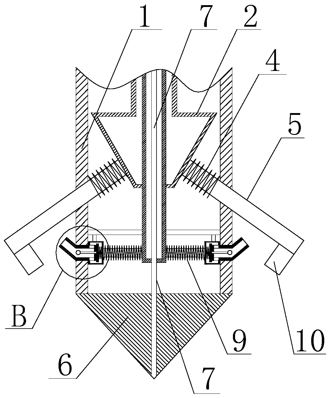
[0041] Such as Figure 1 to Figure 6 Shown, comprise rod body 1 and conical head 6, described conical head 6 is positioned at the bottom end of rod body 1, and described rod body 1 is provided with the spray pipe 7 that communicates with the bottom of conical head 6, is empty in described rod body 1 Cavity structure, the water spray pipe 7 is located in the cavity, the cavity is provided with a slurry delivery pipe 3, and the water spray tube 7 runs through the slurry delivery tube 3; the cavity of the rod body 1 is also provided with movable components 2. The movable assembly 2 is set on the outer wall of the slurry delivery pipe 3, and the movable assembly 2 can move along the axial direction of the slurry delivery pipe 3, and the side walls of the drill blades 5 facing the direction of the conical head 6 are provided with stoppers. Plate 10; the outer peripheral wall of the rod body 1 is also provided with a number of drill blades 5, the drill blades 5 are distributed on th...

Embodiment 2

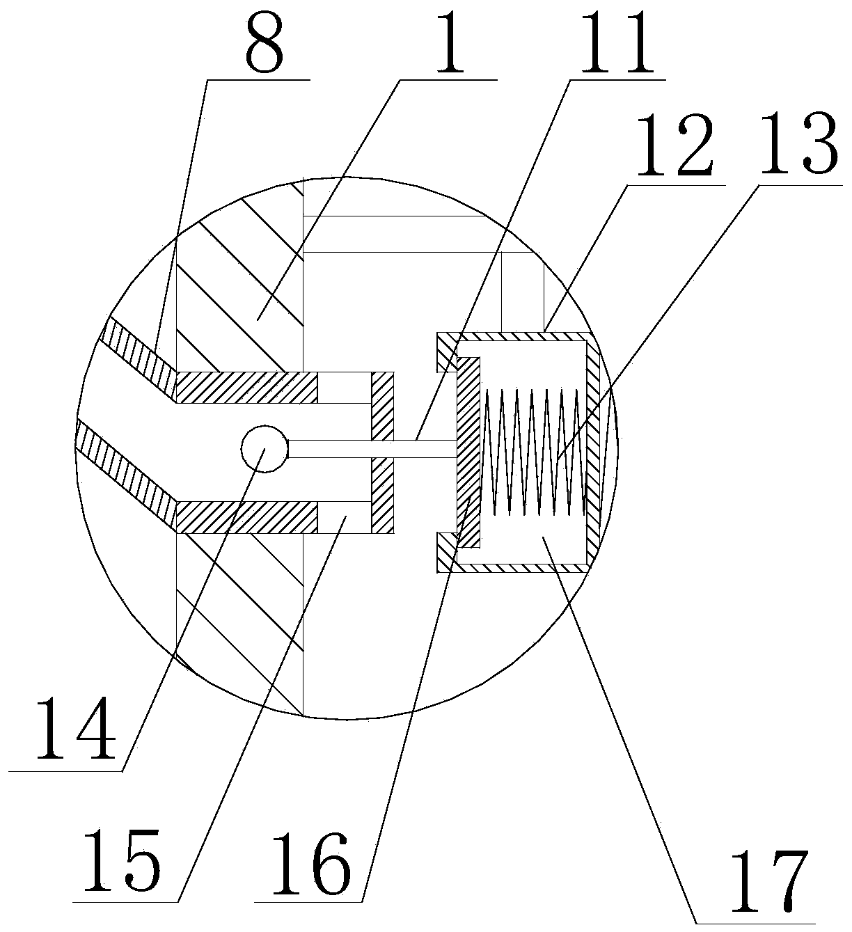
[0043] On the basis of Embodiment 1, the movable assembly 2 includes a conical member 22 and a connecting pipe 20, the conical member 22 is located at the bottom of the connecting pipe 20, and a liquid storage cavity 21 is arranged in the conical member 22, and the liquid storage The cavity 21 communicates with the connecting pipe 20, and the slurry delivery pipe 3 is inserted through the connecting pipe 20 and the liquid storage chamber 21 in sequence.

Embodiment 3

[0045] On the basis of Embodiment 1, the drill blade 5 is further provided with a first elastic member 4 , and the first elastic member 4 is sleeved on the drill blade 5 and located in the cavity of the rod body 1 .


PUM


Abstract

The invention discloses a high-pressure jet grouting pile drill bit based on road and bridge construction application. The high-pressure jet grouting pile drill bit comprises a rod body and a conicalhead, wherein the rod body is of a cavity structure, and a slurry conveying pipe is arranged in the cavity; a movable assembly is further arranged in the cavity of the rod body, a plurality of drill blades are further arranged on the circumferential outer wall of the rod body, when the movable assembly moves in the direction of the conical head, the movable assembly can push the drill blades to move in the direction away from the rod body, and baffles are arranged on the side walls, facing the conical head, of the drill blades; and telescopic pipes are further arranged in the cavity of the rodbody, one ends of the telescopic pipes communicate with the slurry conveying pipe, a connector is arranged at the other ends of the telescopic pipes, sprayer assemblies as many as the drill blades are further arranged on the circumferential outer wall of the rod body, one ends of the sprayer assemblies face the drill blades, and the other ends of the sprayer assemblies are located in the cavity of the rod body. According to the high-pressure jet grouting pile drill bit, the diameter of a pile hole drilled through the drill bit can be adjusted, different use requirements are met, meanwhile, itis guaranteed that in the downward drilling process of the drill bit, mud and stone in soil can be prevented from blocking the slurry conveying pipe, and therefore the construction efficiency is improved.

Description

technical field [0001] The invention relates to the technical field of road and bridge construction equipment, in particular to a high-pressure rotary grouting pile drill bit based on road and bridge construction applications. Background technique [0002] High-pressure rotary grouting piles use high-pressure rotating nozzles to spray cement slurry into the soil layer and mix with the soil to form a continuous lapped cement reinforcement. The construction area is small, the vibration is small, the noise is low, and it has the advantages of saving wood and steel, durable, and low cost. It has been widely used in the basic engineering of hydraulic construction, industrial construction, civil construction and bridges. The high-pressure rotary grouting pile is to use a drilling rig to drill the rotary grouting pipe and the nozzle at the design elevation of the pile bottom, pass the pre-prepared grout through the high-pressure generating device to make the liquid flow obtain huge...

Claims


Application Information

Patent Timeline
Patent Type & Authority Applications(China)
IPC IPC(8): E21B10/32E21B10/60E21B10/61E21B12/00
CPCE21B10/32E21B10/60E21B10/61E21B12/00
Inventor 李义政
Owner SHANGHAI YUANFENG UNDERGROUND ENG TECH
Why Eureka
Try Eureka