Gas protection method applied to pouring process of middle column pipe and device thereof

A gas protection device and gas protection technology are applied in the direction of casting molten material containers, manufacturing tools, metal processing equipment, etc., which can solve problems such as trouble, steelmaking quality decline, and material ejection to the outside of the shell, so as to improve removal efficiency, Promote the effect of collision growth and convenient operation

Inactive Publication Date: 2020-05-15
马鞍山市星新机械材料有限公司
View PDF7 Cites 2 Cited by
  • Summary
  • Abstract
  • Description
  • Claims
  • Application Information

AI Technical Summary

Problems solved by technology

[0002] In the prior art, when pouring steelmaking, due to the direct contact between the poured molten steel and the air, it will cause secondary oxidation of the poured molten steel, resulting in a decline in the quality of steelmaking. Gas shield, which can prevent the quality decline caused by the secondary oxidation of molten steel to a certain extent, but the conditions in the cavity cannot be observed, resulting in reduced reliability; and due to the limited height of the pick-and-place opening, it cannot It further cooperates with the output port of the molten steel pouring device, so that the material is often ejected to the outside of the shell during pouring, which affects the reliability of use; and the position of the connecting pipe is fixed, because it cannot be rotated and adjusted, causing it to be in contact with the argon gas. It is very troublesome to move the whole shell when manufacturing or matching the storage device

Method used


Image

  • Gas protection method applied to pouring process of middle column pipe and device thereof
  • Gas protection method applied to pouring process of middle column pipe and device thereof
  • Gas protection method applied to pouring process of middle column pipe and device thereof

Examples


Embodiment Construction

[0017] Below in conjunction with accompanying drawing and specific embodiment, further illustrate the present invention, should be understood that these embodiments are only for illustrating the present invention and are not intended to limit the scope of the present invention, after having read the present invention, those skilled in the art will understand various aspects of the present invention Modifications in equivalent forms all fall within the scope defined by the appended claims of this application.

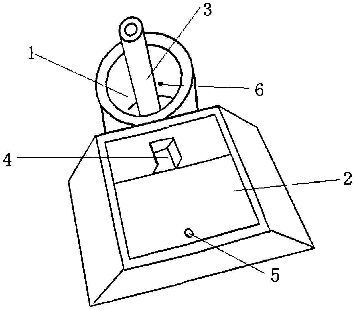
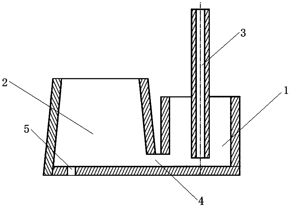
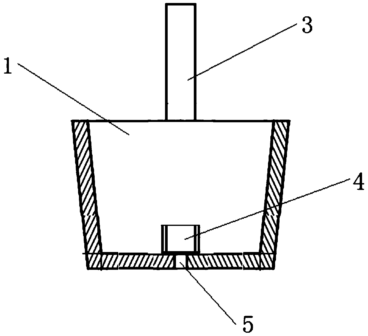
[0018] The present invention is applied to the gas protection method of the middle column pipe pouring process, comprising the following steps:

[0019] Step 1: When the molten steel has not flowed into the ladle 1, the inert gas is introduced into the ladle 1 through the vent 4 at the bottom of the ladle 1 until all the molten steel flows into the ladle 1, and the blowing direction of the inert gas is towards the direction of the swirling flow of the molten steel Horizo...


PUM


Abstract

The invention provides a gas protection method applied to a pouring process of a middle column pipe and a device thereof. The method comprises the following steps of step 1, when molten steel does notflow into a steel ladle, introducing inert gas into the steel ladle through a vent at the bottom of the steel ladle until the molten steel completely flows into the steel ladle, wherein the gas blowing direction of the inert gas is similar to the horizontal tangential direction of the rotational flow of the molten steel; step 2, stopping introducing the inert gas into the vent, and feeding the purified molten steel in the steel ladle into a molten steel tundish through the vent; and step 3, opening a water port at the bottom of the molten steel tundish so as to inject the molten steel in themolten steel tundish into a crystallizer for solidification forming. Compared with a conventional pouring process of the middle column pipe, the gas protection method has the advantages that the steelladle is arranged at the outer side; the molten steel realizes rotating flowing through gas driving, so that the collision enlarging of inclusions is promoted; the upward floating removal of the inclusions is facilitated; and the removal efficiency of the inclusions is greatly improved.

Description

technical field [0001] The invention belongs to the field of metallurgical technology and devices thereof, and in particular relates to a gas protection method and a device thereof applied in the pouring process of a central column tube. Background technique [0002] In the prior art, when pouring steelmaking, due to the direct contact between the poured molten steel and the air, it will cause secondary oxidation of the poured molten steel, resulting in a decline in the quality of steelmaking. Gas shield, which can prevent the quality decline caused by the secondary oxidation of molten steel to a certain extent, but the conditions in the cavity cannot be observed, resulting in reduced reliability; and due to the limited height of the pick-and-place opening, it cannot It further cooperates with the output port of the molten steel pouring device, so that the material is often ejected to the outside of the shell during pouring, which affects the reliability of use; and the posi...

Claims


Application Information

Patent Timeline
Patent Type & Authority Applications(China)
IPC IPC(8): C21C7/072B22D41/58
CPCB22D41/507B22D41/58C21C7/072
Inventor 谢德金孙昌虎王凌刚胡学武
Owner 马鞍山市星新机械材料有限公司
Why Eureka
Try Eureka