
Box structure based on cold plate

A box structure and cold plate technology, which is applied in cooling/ventilation/heating transformation, casing/cabinet/drawer components, antennas, etc., can solve the limited miniaturization of the antenna structure, the difficulty of structural design and the technical requirements Improvement and other issues to achieve the effect of reducing the size and simplifying the complexity

Inactive Publication Date: 2020-05-12
THE 724TH RES INST OF CHINA SHIPBUILDING IND
View PDF7 Cites 0 Cited by
  • Summary
  • Abstract
  • Description
  • Claims
  • Application Information

AI Technical Summary

Problems solved by technology

This type of structure needs to add relevant structures inside the antenna frame to install the cold plate, which not only increases the difficulty of structural design and process requirements, but also limits the miniaturization of the antenna structure.

Method used


Image

  • Box structure based on cold plate
  • Box structure based on cold plate
  • Box structure based on cold plate

Examples


Embodiment Construction

[0013] The present invention will be further described below in conjunction with accompanying drawing.

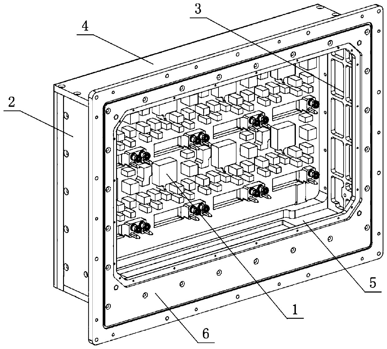
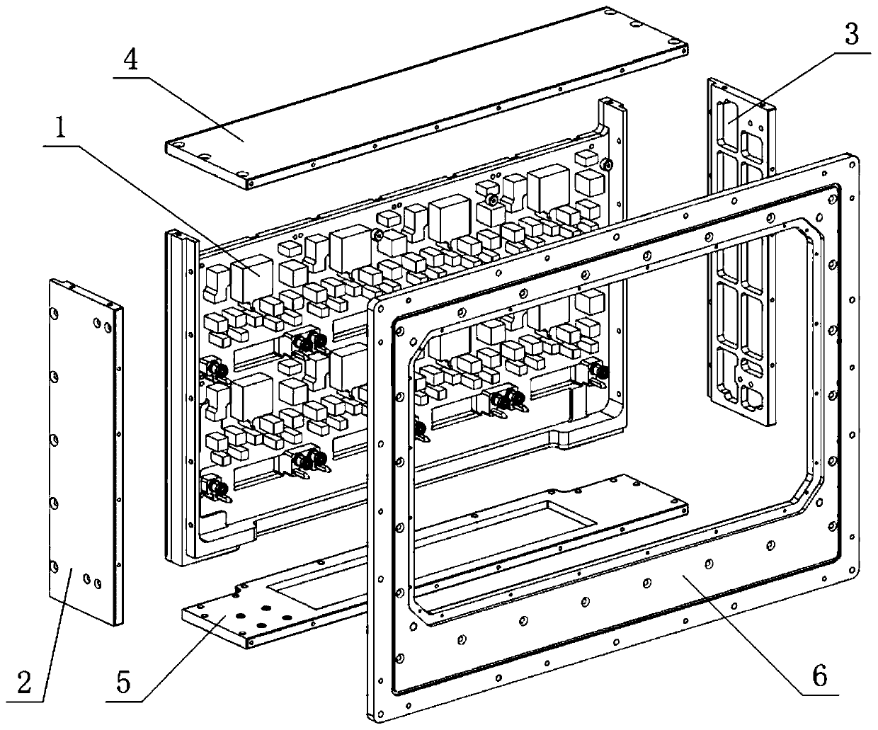
[0014] like figure 1 and figure 2 As shown, the antenna box structure is based on the cold plate 1, and the left frame 2, the right frame 3, the upper frame 4 and the lower frame 5 are respectively installed on the lapping surfaces around the cold plate 1, and the front ends of the above four frames are The surfaces are on the same plane, and are embedded in the ring-shaped platform at the back of the flange frame 6, and connected with the flange frame 6 by screws.

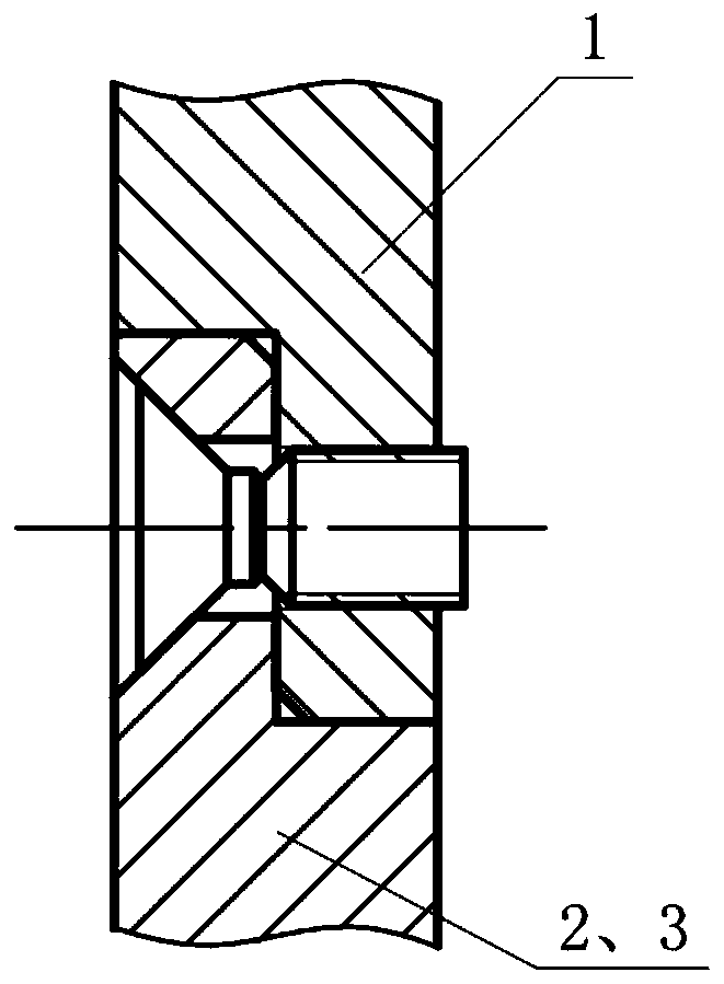
[0015] The cold plate 1 is H-shaped, and the middle area is distributed with inlet and outlet channels and cooling and heat dissipation areas to dissipate heat from the relevant heating components inside the box; the thickness of the two side areas and the bottom area of ​​the cold plate 1 is increased compared with the middle area, and the thickness is similar to that of the middle area. The left frame 2 an...


PUM


Abstract

The invention belongs to the field of universal structures of electrical equipment, and provides a box body structure based on a cold plate. The box body structure is used as a shell structure of theelectrical equipment and is assembled with glue based on the cold plate. The box body structure is based on the cold plate, and a left frame, a right frame, an upper frame and a lower frame are installed on the lap joint faces of the periphery of the cold plate respectively; the front end faces of the frames are kept on the same plane, a flange frame is installed on the plane, and the installationfaces of all parts are in a step shape and play a role in positioning and sealing. The cold plate is a component of the box body structure, so the box body structure has heat dissipation capability,the complexity of the antenna structure is simplified, and the boundary dimension of the box body structure is further reduced. The box body structure can be used for an electrical equipment shell structure with cooling and heat dissipation requirements, especially a small electrical equipment shell structure with a limited boundary dimension.

Description

technical field [0001] The invention belongs to the field of general structure of electrical equipment. Background technique [0002] The frame structure of the phased array antenna is an important part of the phased array antenna. The antenna frame is not only used as a load-bearing part, and the array antenna unit is installed inside; at the same time, it is used as the outer shell of the antenna to protect the internal T / R components and other microwave integrated circuits. Due to the increasing density of microwave integrated circuits such as T / R components installed inside the active phased array antenna, and the microwave integrated circuits such as T / R components generate a lot of heat during operation, the internal temperature of the antenna rises sharply. How to efficiently dissipate heat from the active phased array antenna and ensure the normal operation of the antenna is increasingly important. With the miniaturization of T / R components, the heat dissipation re...

Claims


Application Information

Patent Timeline
Patent Type & Authority Applications(China)
IPC IPC(8): H05K7/20H05K5/02H05K5/06H01Q1/00
CPCH01Q1/02H05K5/0217H05K5/061H05K7/2039
Inventor 李舒陈伟晏腾飞李荣
Owner THE 724TH RES INST OF CHINA SHIPBUILDING IND
Learn More