Heat treatment device for automobile part machining

A technology for heat treatment devices and auto parts, applied in heat treatment furnaces, heat treatment equipment, heat treatment process control, etc., can solve the problems that pit furnaces are difficult to meet processing requirements and temperature uniformity is difficult to control, and achieve small footprint, simple structure, The effect of reducing the renovation cost

Pending Publication Date: 2020-05-12
ZHOUSHAN 7412 FACTORY
View PDF1 Cites 0 Cited by
  • Summary
  • Abstract
  • Description
  • Claims
  • Application Information

AI Technical Summary

Problems solved by technology

However, when this pit furnace is used for tempering or aging treatment of auto parts, under the high-speed rotation of the fan, only the gas in the furnace in the upper zone is rotating, and the gas in the furnace in the middle and lower zones is not rotating, forming a dead angle , so that the temperature uniformity in the furnace is difficult to control within ±20°C, and when the well-type furnace is used for tempering or aging treatment of auto parts, the furnace temperature uniformity must be within ±5°C, and the well-type furnace is difficult to meet the processing requirements , so the structure of the pit furnace needs to be further improved

Method used


Image

  • Heat treatment device for automobile part machining
  • Heat treatment device for automobile part machining
  • Heat treatment device for automobile part machining

Examples


Embodiment Construction

[0019] The present invention will be further described in detail below in conjunction with the accompanying drawings and embodiments.

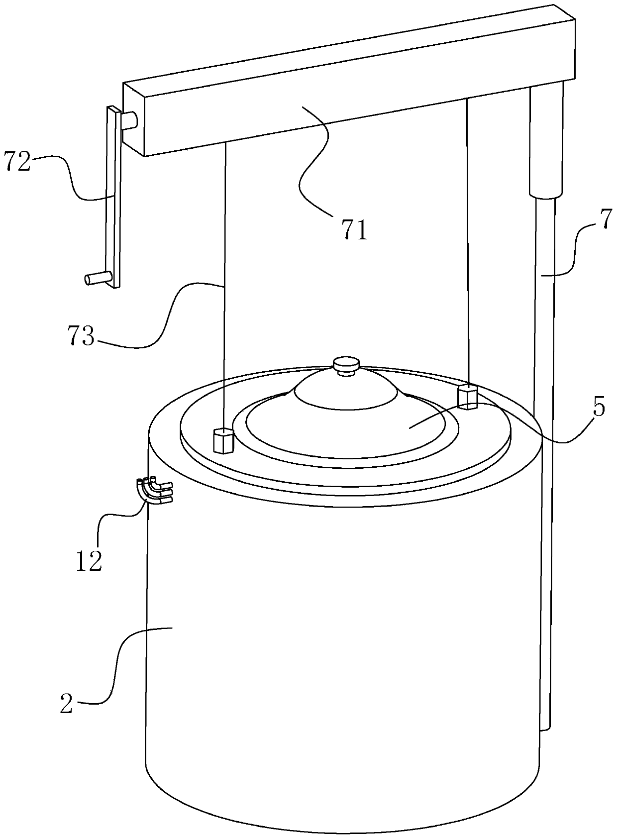
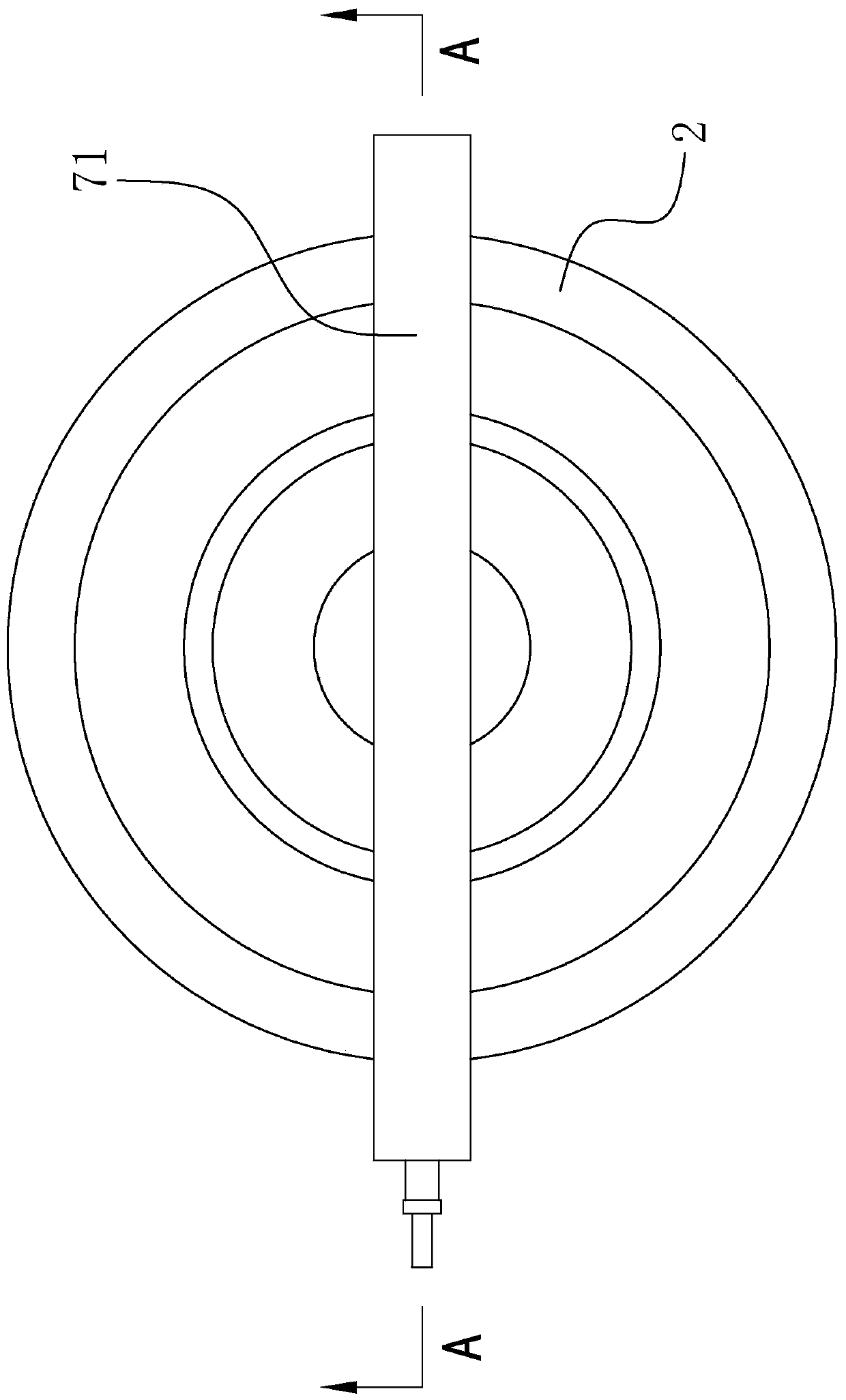
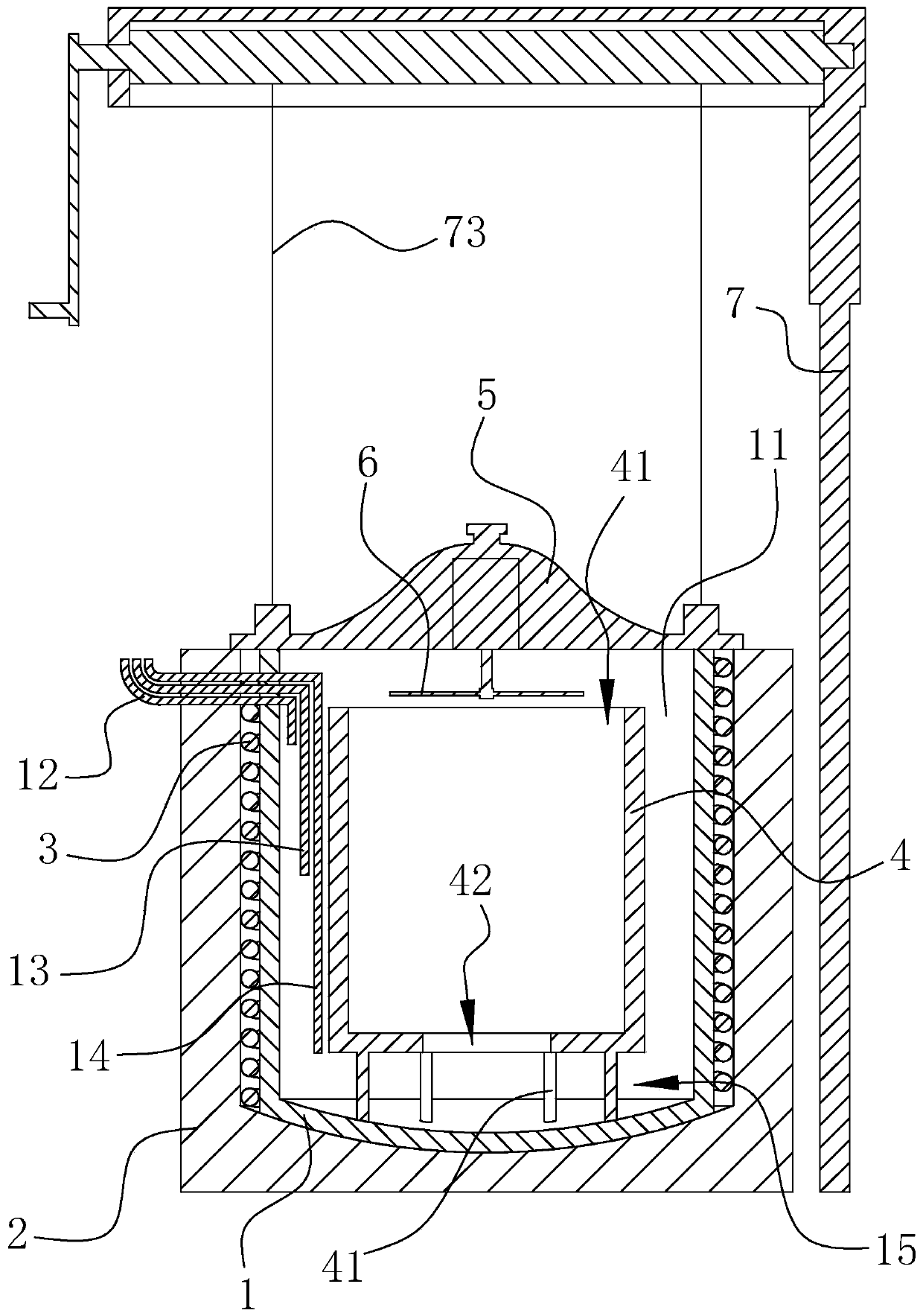
[0020] Such as Figure 1 to Figure 4 As shown, the heat treatment device for the processing of automobile parts in this embodiment includes a furnace body, a furnace cover 5 positioned at the top of the furnace body, a fan 6 arranged on the furnace cover 5 and a lifting mechanism for opening and closing the furnace cover 5, In the furnace chamber 11 of the body of heater, a diversion sleeve 4 is arranged, and the top and bottom of the diversion sleeve 4 are open, and the inner chamber of the diversion sleeve 4 is connected with the upper furnace cavity through the top opening 41, and the inner chamber of the diversion sleeve 4 The bottom opening 42 communicates with the lower furnace chamber, and there is a gap through which air can pass between the bottom surface of the diversion sleeve 4 and the bottom surface of the furnace chamber 11. The ...


PUM


Abstract

The invention relates to a heat treatment device for automobile part machining. The heat treatment device comprises a furnace body, a furnace cover located at the top of the furnace body, a fan arranged on the furnace cover and a lifting mechanism used for opening and closing the furnace cover; a flow guide sleeve is arranged in a furnace cavity of the furnace body, openings are formed in the topand the bottom of the flow guide sleeve, and an inner cavity of the flow guide sleeve communicates with the upper furnace cavity through the opening in the top, the inner cavity of the flow guide sleeve is communicated with the lower furnace cavity through the opening in the bottom, a gap allowing air to pass through is reserved between the bottom face of the flow guide sleeve and the bottom faceof the furnace cavity, and the fan sucks the air in the flow guide sleeve into the upper furnace cavity so that the air in the middle-lower furnace cavity can flow into the inner cavity of the flow guide sleeve to form air circulation flowing up and down. The heat treatment device has the advantages that the flow guide sleeve strengthens up-and-down convection of the air in the furnace cavity, up-and-down convection circulation of the whole furnace cavity is formed in the furnace cavity, the uniformity of the temperature in the furnace cavity is effectively improved, and the temperature difference between the upper furnace cavity and the lower furnace cavity is within + / -2 DEG C during heating.

Description

technical field [0001] The invention relates to a heat treatment device, in particular to a heat treatment device used for processing automobile parts. Background technique [0002] An existing Chinese utility model patent with the application number CN201220464545.4 titled "Pit Furnace" discloses a well-type furnace, which includes a furnace body and a furnace cover on the top of the furnace body, and the furnace cover is provided with a fan , the lifting device used for opening and closing the furnace cover on the furnace body; since the utility model is provided with a fan on the furnace cover, when heating, under the action of the fan, the fan can move the hot air on the upper part of the furnace body to The lower part of the furnace body is blown, so that the hot air flows up and down in the furnace body, so that the overall temperature of the furnace body is more uniform, the value measured by the thermocouple is more accurate, and the blanks at each position are at th...

Claims


Application Information

Patent Timeline
IPC IPC(8): C21D9/00C21D11/00C21D1/74
CPCC21D9/00C21D9/0006C21D11/00C21D1/74
Inventor 唐建良洪军锋周兵潘冬杰
Owner ZHOUSHAN 7412 FACTORY
Why Eureka
Try Eureka