Wedging type stamping part capable of achieving automatic positioning

An automatic positioning and stamping technology, applied in positioning devices, metal processing equipment, feeding devices, etc., can solve the problems of manual placement and fixation of stamping parts, inability to fix stamping parts, waste of manpower and time, etc., to improve the use of Longevity, improved accuracy, and improved work efficiency

Inactive Publication Date: 2020-05-12
湖州欣久利机械有限公司
View PDF0 Cites 2 Cited by
  • Summary
  • Abstract
  • Description
  • Claims
  • Application Information

AI Technical Summary

Problems solved by technology

[0004] The present invention provides a fitting stamping part that can be automatically positioned, which can effectively solve the problem that the stamping part proposed in the above background technology needs to be manually placed and fixed, which wastes manpower and time, and cannot accurately fix the stamping part, resulting in stamping failure.

Method used


Image

  • Wedging type stamping part capable of achieving automatic positioning
  • Wedging type stamping part capable of achieving automatic positioning
  • Wedging type stamping part capable of achieving automatic positioning

Examples


Embodiment

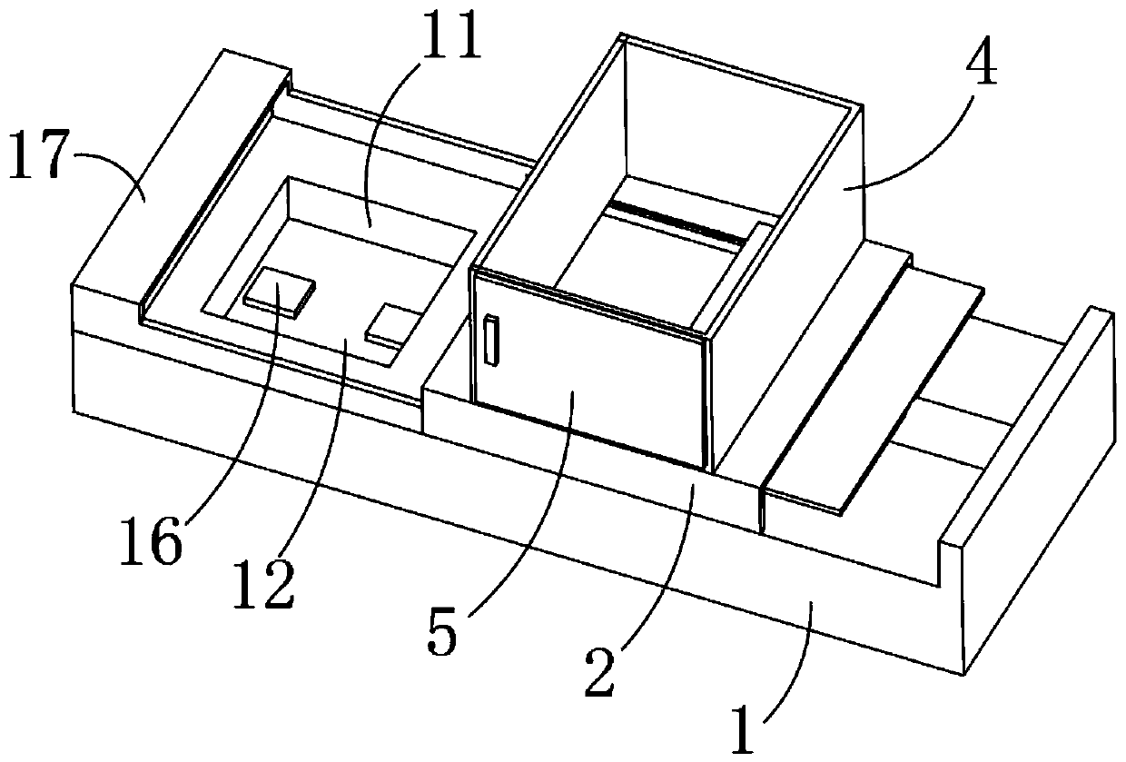
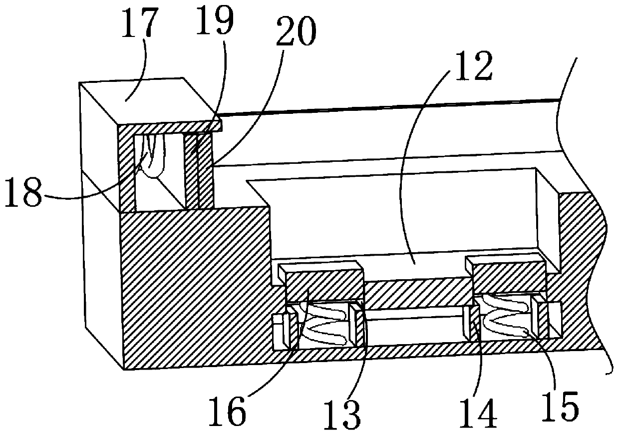
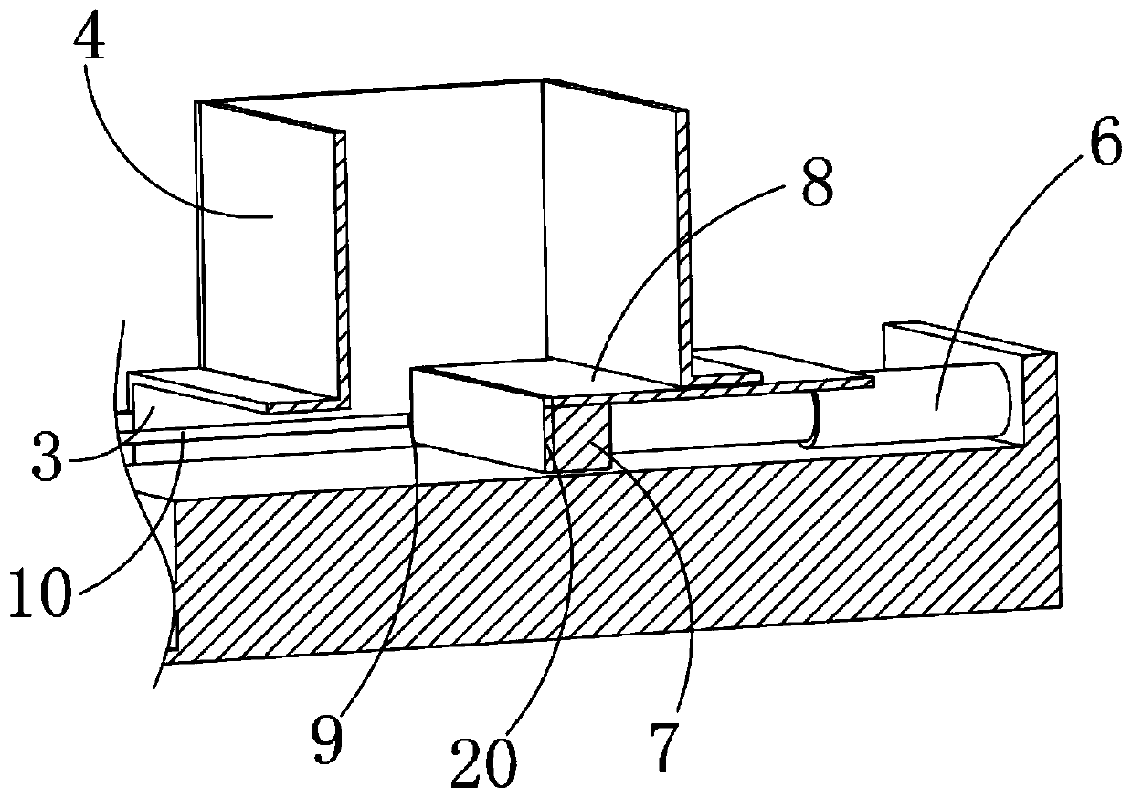
[0023] Example: such as Figure 1-3 As shown, the present invention provides a technical solution, a fitting stamping part that can be automatically positioned, a support seat 2 is installed in the middle of the top of the base 1, a through groove 3 is opened inside the support seat 2, and the top of the support seat 2 is installed There is a discharge box 4, a discharge door 5 is installed at one end of the discharge box 4, an electro-hydraulic rod 6 is installed at one end of the top of the base 1, and an extrusion block 7 is connected to one end of the electro-hydraulic rod 6, and the extrusion block 7 The top of the baffle 8 is connected with a baffle 8, the top of the baffle 8 fits the bottom of the discharge box 4, and the extrusion block 7 pushes the stamping parts forward, the baffle 8 ensures that the inside of the discharge box 4 The stamping plate will not fall downwards, the input end of the electro-hydraulic rod 6 is electrically connected to the output end of the...


PUM


Abstract

The invention discloses a wedging type stamping part capable of achieving automatic positioning. A through groove is formed in a supporting seat, a discharging box body is mounted at the top of the supporting seat, a discharging door is mounted at one end of the discharging box body, an electric hydraulic rod is mounted at one end of the top of a base, an extrusion block is connected to one end ofthe electric hydraulic rod, a baffle is connected to the top of the extrusion block, clamping blocks are symmetrically installed on the two side portions of the extrusion block, clamping grooves aresymmetrically formed in the two side walls of the interior of the supporting seat, a stamping die cavity is formed in the position, located on one side of the supporting seat, of the top of the base,a fixing plate is installed in the middle of the stamping die cavity, and grooves are symmetrically formed in the middle of the fixing plate. Through cooperative use of the electric hydraulic rod andthe extrusion block, the stamping part is pushed to the stamping area, an operator is prevented from manually placing the stamping part, the working efficiency is improved, and meanwhile the stampingpart in the discharging box body is prevented from falling off in the stamping process through the baffle.

Description

technical field [0001] The invention relates to the technical field of stamping equipment, in particular to a fitting stamping part that can be automatically positioned. Background technique [0002] Stamping processing mainly uses the impact force of stamping equipment to extrude the stamping parts, so that the plate is deformed by the impact force in the mold to obtain a finished product with a certain shape, size and performance. At present, most of the stamping equipment used by domestic enterprises are manual. The operation depends on manually picking and placing workpieces and controlling the production rhythm. For this reason, a Chinese patent discloses a stamping machine tool with an application number of 201721912711.1. The device is equipped with a soundproof cotton interlayer through the side walls of the first protective door and the second protective door. , effectively absorb the collision noise generated during the working process of the punching machine, grea...

Claims


Application Information

Patent Timeline
Patent Type & Authority Applications(China)
IPC IPC(8): B21D43/20B21D43/04B21D43/00B21D45/04
CPCB21D43/003B21D43/04B21D43/20B21D45/04
Inventor 阳新江
Owner 湖州欣久利机械有限公司
Why Eureka
Try Eureka