Lighting module for motor vehicles with ground connection

A technology for light-emitting modules and motor vehicles, which is applied in the directions of motor vehicles, road vehicles, and vehicle components to achieve the effect of saving volume and low manufacturing cost

Active Publication Date: 2021-12-07
VALEO VISION SA
View PDF21 Cites 0 Cited by
  • Summary
  • Abstract
  • Description
  • Claims
  • Application Information

AI Technical Summary

Problems solved by technology

However, electronic circuits fabricated on the face of an FPCB may need to be connected to zero potential or ground

Method used


Image

  • Lighting module for motor vehicles with ground connection
  • Lighting module for motor vehicles with ground connection
  • Lighting module for motor vehicles with ground connection

Examples


Embodiment Construction

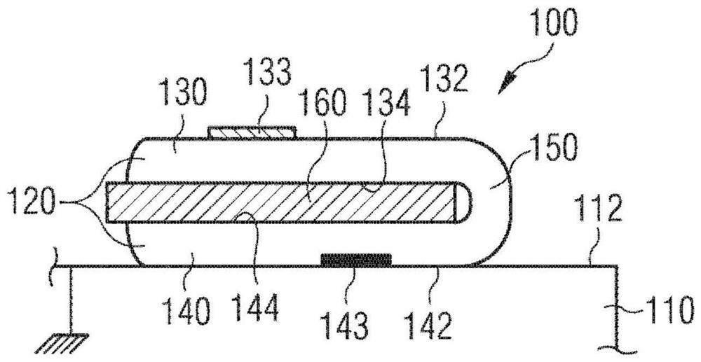
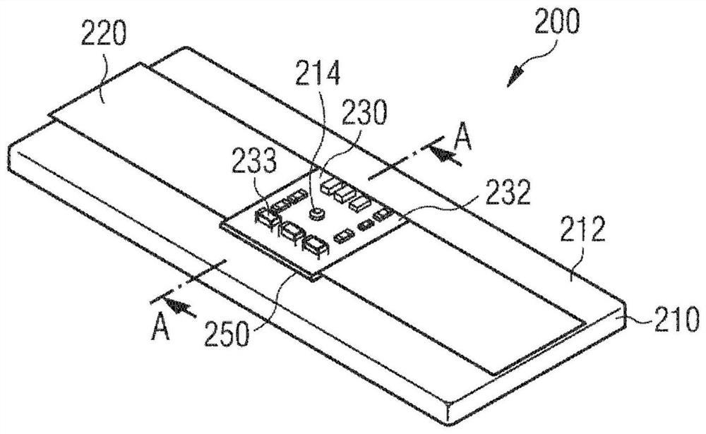
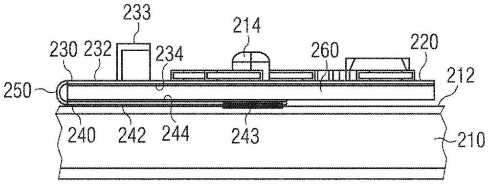
[0028] In the following description, like reference numerals will be used to describe like concepts throughout the various embodiments of the present invention. Thus, reference numerals 100, 200, 300, 400 describe lighting modules in four different embodiments according to the invention.

[0029] Unless specifically stated otherwise, features described in detail for a given embodiment may be combined with features described in the context of other embodiments described by way of example and not limitation.

[0030] Elements shown in the figures are not to scale and have been simplified for clarity of description.

[0031] Flexible printed circuit boards (FPCBs) are known per se in the prior art. Their manufacture will not be described in detail in the context of the present invention. Typically, the components of the electronic circuit implanted on the FPCB are placed on the first side of the board and connected by conductive traces provided on the surface of the board. In ...


PUM


Abstract

The present invention proposes a light emitting module including a flexible printed circuit board. The connection to ground of the electronic circuit housed by the printed circuit board is produced without adding fixed parts dedicated to this function. Compared to the known prior art, the invention allows the production of lighting modules comprising fewer component parts and occupying a smaller volume.

Description

technical field [0001] The invention relates to the field of lighting and luminous signaling, in particular in motor vehicles. Background technique [0002] In the field of lighting and luminous signaling for motor vehicles, the use of light sources comprising light-emitting semiconductor elements, such as light-emitting diodes (LEDs), has become more and more frequent. The LED element emits light when a voltage having a value at least equal to a threshold value called a turn-on voltage is applied to these terminals. [0003] As is known, one or more LEDs of a lighting module for a motor vehicle are powered with a supply control device comprising a converter circuit. The supply control device is configured to convert a current of a first magnitude, eg delivered by a current source of the motor vehicle, such as a battery, into a load current of a second magnitude different from the first magnitude. As is known, the electronic circuit forming the supply control means and the...

Claims


Application Information

Patent Timeline
Patent Type & Authority Patents(China)
IPC IPC(8): F21S41/00F21S45/48F21V17/10F21V23/00F21Y115/10F21W102/00
CPCF21V29/87F21S43/00F21V17/101F21V23/003F21W2107/10H05K1/0204H05K1/0209H05K1/0215H05K1/028H05K3/0061H05K2201/055H05K2201/056H05K2201/066H05K2201/10106H05K2201/10401F21S45/49F21S45/47H05K1/189F21V19/003H05K1/147
Inventor 奥利维尔·巴迪亚
Owner VALEO VISION SA
Why Eureka
Try Eureka