


Quick Research
Generate reliable direction feasibility study reports for your R&D in just a few steps.

Technical Q&A
Discover and master advanced knowledge NOW. Basics, ideas, possibilities, all at once.

Find Solutions
As an expert in R&D theories, this can generate solutions to your technical problems instantly.

Evaluate Feasibility
Analyze your overall solution with one click, know your potential R&D risks in advance.

Monitor Landscape
Get weekly tech updates, stay abreast of the latest tech innovations and key insights.
Steel bar positioning and binding assembly
A component and steel bar technology, applied in the field of steel bar positioning and binding components, can solve the problems of high labor cost and low efficiency, and achieve the effect of reasonable structure
- Summary
- Abstract
- Description
- Claims
- Application Information
AI Technical Summary
Problems solved by technology
Method used
Image

Examples
Embodiment 1
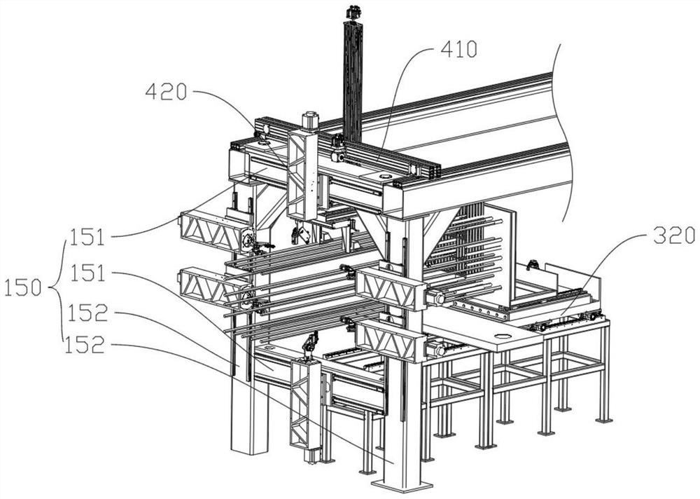
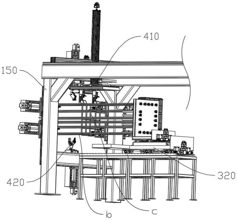
[0035] like Figure 1-7As shown in the figure, the reinforcing bar positioning and binding assembly of Embodiment 1 includes a frame, a reinforcing bar cage binding unit connected to the frame, and a stirrup material box 910 for stacking stirrup groups, and several longitudinal bars pass through the frame. In the stirrup magazine 910; the reinforcement cage binding unit includes a stirrup moving component 410 for moving the stirrups on the stirrup magazine 910 to the binding position one by one, and a stirrup moving assembly 410 for moving the stirrups on the binding position one by one. The binding robot 420 bound with the longitudinal bars, the stirrup material box 910 , the stirrup moving assembly 410 and the binding robot 420 are arranged in sequence along the conveying direction of the longitudinal bars.
[0036] The frame includes a fixed binding truss 150 , and the binding robot 420 is connected to the binding truss 150 .
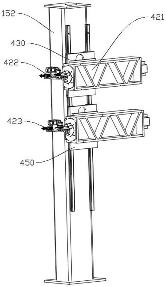
[0037] The binding robot 420 includes a bindi...
Embodiment 2
[0054] like Figure 8-13 As shown, Embodiment 2 is based on Embodiment 1, except that: the frame includes a stirrup truss 120; 820, the claw seat 810 is slidably matched with the stirrup truss 120, and between the claw seat 810 and the stirrup truss 120 is provided for driving the claw seat 810 between the stirrup material box 910 and the binding position. The claw seat drive assembly that reciprocates between them.
[0055] The stirrup grasping member 820 includes a lower transverse claw 821 fixedly connected with the claw seat 810 , an upper pressing claw 822 slidably connected with the claw seat 810 , and driving the upper pressing claw 822 and the lower transverse claw. 821 is attached to or separated from the pressing claw driving assembly, and the sliding direction of the upper pressing claw 822 is set vertically.
[0056] The claw driving assembly includes a claw cylinder 823, the cylinder body of the claw cylinder 823 is fixedly connected with the claw seat 810, and ...
PUM
 Abstract
Description
Claims
Application Information
 - R&D Engineer
- R&D Manager
- IP Professional
- Industry Leading Data Capabilities
- Powerful AI technology
- Patent DNA Extraction
Browse by: Latest US Patents, China's latest patents, Technical Efficacy Thesaurus, Application Domain, Technology Topic, Popular Technical Reports.
© 2024 PatSnap. All rights reserved.Legal|Privacy policy|Modern Slavery Act Transparency Statement|Sitemap|About US| Contact US: help@patsnap.com