
Vehicle-mounted traffic cone automatic laying device

A traffic cone and vehicle-mounted technology, which is applied in the field of vehicle-mounted traffic cone automatic deployment devices, can solve problems such as low work efficiency, inconvenient operation, and slow operation speed, and achieve the effects of easy promotion, convenient operation, and simple structure

Inactive Publication Date: 2020-05-08
江门市新会区智华科技服务有限公司
View PDF0 Cites 1 Cited by
  • Summary
  • Abstract
  • Description
  • Claims
  • Application Information

AI Technical Summary

Problems solved by technology

It is conceivable that the manual operation method is not only slow in operation speed and high in labor intensity, but also difficult to unify the stacking interval of traffic cones and low in work efficiency; in particular, it also has the key problem of high hidden danger in operation; especially in the case of heavy traffic flow The above problems are even more prominent when working on urban expressways
At the same time, manual operations are also susceptible to interference from weather and environmental factors, and the risk factor is high in harsh environments such as heavy fog, heavy rainfall or thunderstorms
[0003] In recent years, some traffic cone deployment vehicles have also appeared on the market, which can replace manual work to realize automatic deployment of traffic cones, but in use, it is also found that such traffic cone deployment vehicles have problems such as complex structure and inconvenient operation.
[0004] In addition, as an independent equipment, the traffic cone deployment vehicle is relatively simple in terms of its functions; if the highway department specially adds a special equipment for the deployment of traffic cones in its organizational system, it would be too tasteless, economical and practical. are relatively low; therefore, the promotion degree of existing traffic cone deployment vehicles is actually not high

Method used


Image

  • Vehicle-mounted traffic cone automatic laying device
  • Vehicle-mounted traffic cone automatic laying device
  • Vehicle-mounted traffic cone automatic laying device

Examples


Embodiment Construction

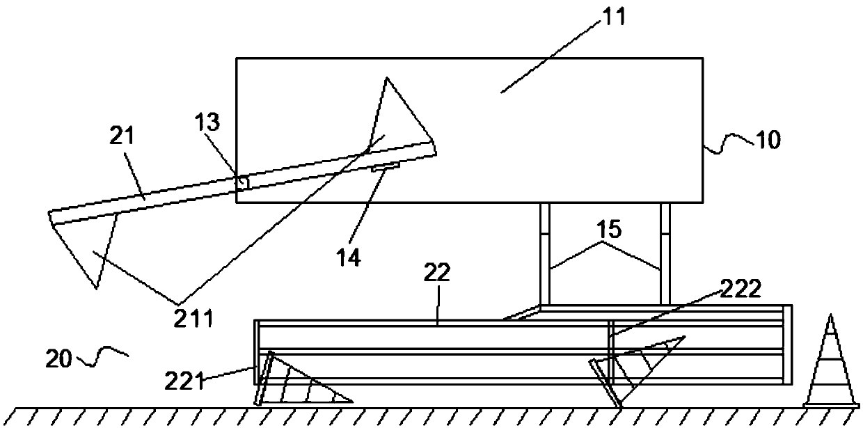
[0021] see Figure 1~2 , a vehicle-mounted traffic cone automatic deployment device, comprising a structure panel 10, a traffic cone deployment mechanism 20; the structure panel includes a first flat plate 11 and a second flat plate 12 perpendicular to each other; the traffic cone deployment The mechanism 20 is fixedly connected to the first flat plate 11; the traffic cone deployment mechanism includes a turning plate 21 and a guide frame 22; a pair of conical protrusions 211 are provided on the surface of the turning plate at both ends, and the tapered The protrusions 211 are respectively located on the plate surface of the opposite side of the turning lever 21, and the side of the turning plate 21 in the middle is connected with the first flat plate 11 through a rotating shaft 13, and the turning 21 plate can be carried out with the rotating shaft 13 as the center. Rotation; the first flat plate 11 is provided with a preparatory position shrapnel 14 that limits the idling of...


PUM


Abstract

The invention relates to a vehicle-mounted traffic cone automatic laying device. By ingeniously arranging a turnover plate, a preparation position elastic piece and a guide frame, after the traffic cone is located on the conical protrusion on the turnover plate, the turnover plate breaks through the limitation of the preparation position elastic piece due to the gravity effect of the traffic coneto rotate, and the traffic cone is transversely arranged on the road surface after the separation limiting effect of the guide frame; along with the continuous advancing of the vehicle, the supportinglimit of the guide frame reaches the position of the traffic cone and acts on the base of the traffic cone to erect the traffic cone. The device is simple in structure and convenient to operate; meanwhile, the vehicle-mounted traffic cone automatic laying device can directly utilize an old engineering vehicle and carry out equipment installation on the old engineering vehicle, equipment construction of related units does not need to be occupied, and the vehicle-mounted traffic cone automatic laying device is easier to popularize.

Description

technical field [0001] The invention relates to the technical field of road traffic construction, in particular to a vehicle-mounted automatic deployment device for traffic cones. Background technique [0002] In our country, during the maintenance work on the expressway, in order to realize the temporary closure of the road, it is often necessary to use traffic cones to cut off the road. Currently, most of the placement of traffic cones is done manually. It is conceivable that the manual operation method is not only slow in operation speed and high in labor intensity, but also difficult to unify the stacking interval of traffic cones and low in work efficiency; in particular, it also has the key problem of high hidden danger in operation; especially in the case of heavy traffic flow The above problems are even more prominent when working on urban expressways. At the same time, the manual operation method is also easily disturbed by weather and environmental factors, and t...

Claims


Application Information

Patent Timeline
IPC IPC(8): E01F9/70
CPCE01F9/70
Inventor 曾妙玲
Owner 江门市新会区智华科技服务有限公司
Learn More