
Rotary extrusion waste aluminum recovery device

A technology of aluminum recycling and aluminum extrusion, applied in the direction of presses, manufacturing tools, etc., can solve the problems that affect the recycling process of waste aluminum, reduce the work efficiency of staff, and the complex structure of recycling devices, and achieve simple extrusion operation, good Effect of airtightness and simplification of extrusion operation

Inactive Publication Date: 2020-05-08
韩峰永
View PDF1 Cites 2 Cited by
  • Summary
  • Abstract
  • Description
  • Claims
  • Application Information

AI Technical Summary

Problems solved by technology

[0003] According to a kind of recycling pretreatment device for waste aluminum products provided by the patent document CN 109266857 A, it can be known that the No. 1 electric control telescopic rod is opened, so that the heated aluminum products fall into the lower side of the processing box through the No. 2 blanking plate. Turn on the No. 2 servo motor, so that the No. 2 servo motor drives the No. 1 connecting rod to move to the left, and drives the No. 2 press plate to extrude the aluminum product horizontally, which is convenient for the next step of processing. However, this product uses a large number of press plates and motors, resulting in Complex structure and cumbersome operation
[0004] The structure of the recycling device is too complicated. When extruding waste aluminum products, the staff need to perform cumbersome operations to complete the purpose of extruding waste aluminum, which reduces the work efficiency of the staff and affects the workflow of waste aluminum recycling. , causing economic losses

Method used

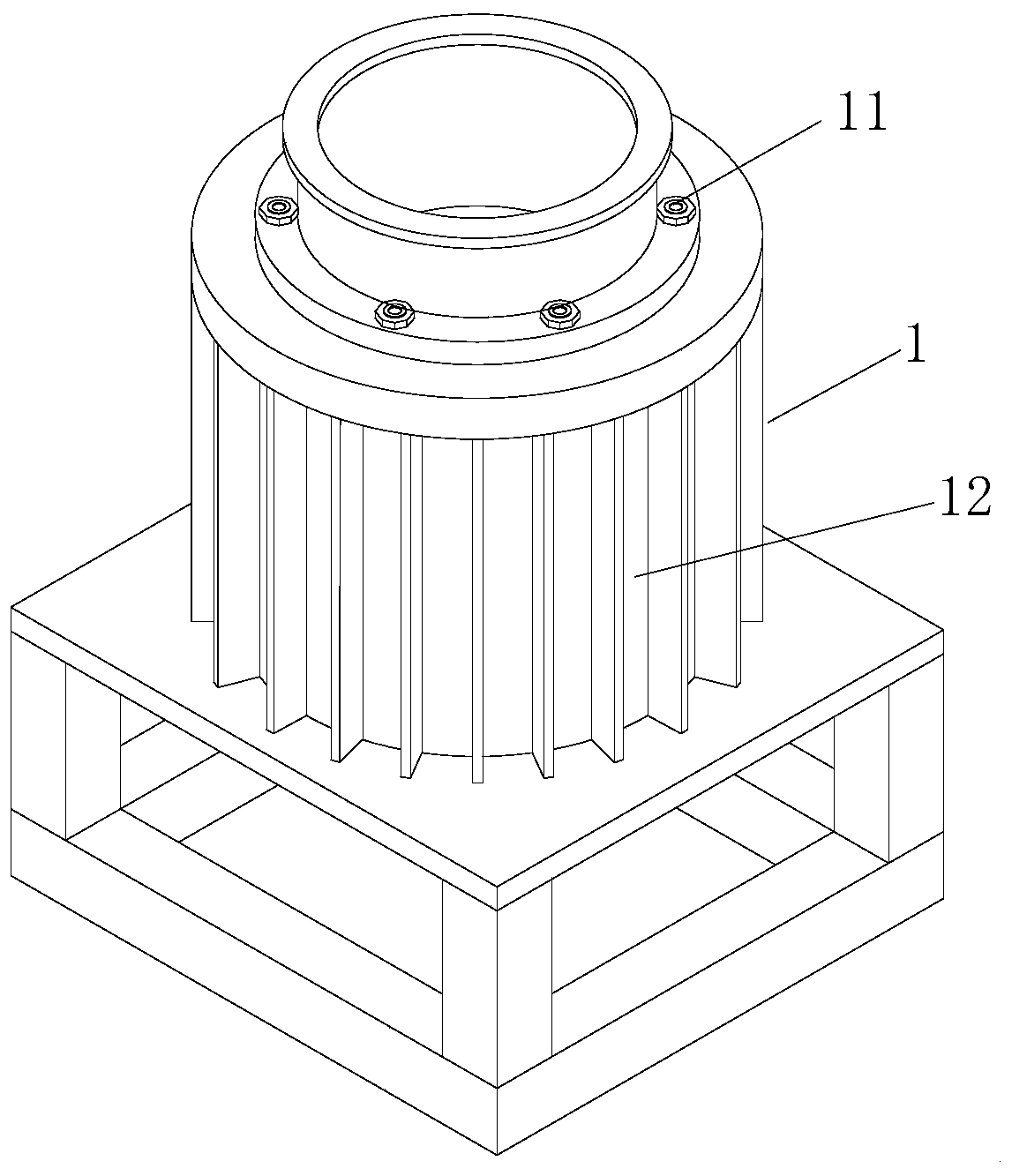

Image

  • Rotary extrusion waste aluminum recovery device
  • Rotary extrusion waste aluminum recovery device
  • Rotary extrusion waste aluminum recovery device

Examples


Embodiment Construction

[0025] In order to facilitate the understanding of the present invention, the present invention will be described more fully below with reference to the relevant drawings, in which several embodiments of the present invention are shown, but the present invention can be realized in different forms, and is not limited to the text described On the contrary, these embodiments are provided to make the disclosure of the present invention more thorough and comprehensive.

[0026] It should be noted that when an element is said to be "fixed on" another element, it can be directly on the other element or there can be an intervening element, and when an element is said to be "connected" to another element, it can be Directly connected to another element or possibly intervening elements at the same time, the terms "vertical," "horizontal," "left," "right," and similar expressions are used herein for purposes of illustration only.

[0027] Unless otherwise defined, all technical and scien...


PUM


Abstract

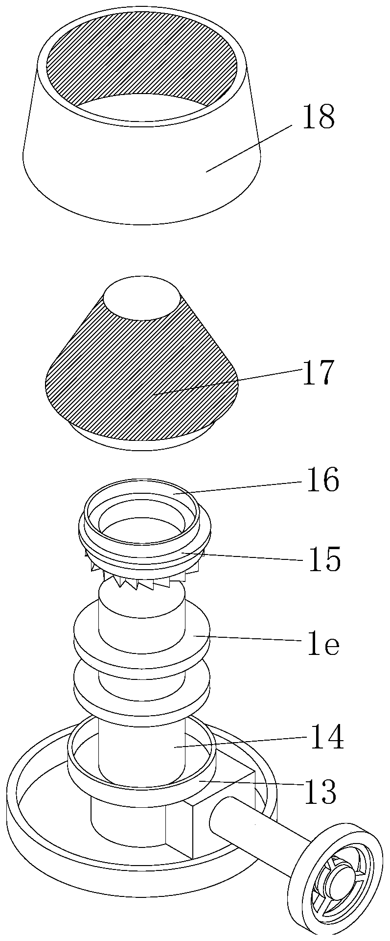
The invention provides a rotary extrusion waste aluminum recovery device which comprises a waste aluminum extrusion assembly. The waste aluminum extrusion assembly comprises an upper shell and a lowershell, the lower shell is positioned at the bottom end of the upper shell and is connected with the upper shell through an air cylinder, the inner wall of the lower shell is connected with an annularslideway through a bolt, a driving shaft is connected in the annular slideway through a key, the outer periphery of the driving shaft is rotatably connected with a first bevel gear through a bearing,the bottom end of the first bevel gear is slidably connected with the annular slideway through a sliding block, the top end of the first bevel gear is provided with an eccentric slideway, the eccentric slideway and the first bevel gear are integrally formed through a die, the top end of the eccentric slideway is slidably connected with an extrusion cone, and the inner wall of the upper shell is connected with a mortar rolling wall. According to the rotary extrusion waste aluminum recovery device, the extrusion cone can complete the extrusion of the material between the extrusion cone and themortar rolling wall through the matching of the extrusion cone and the mortar rolling wall, so that the extrusion operation is simplified.

Description

technical field [0001] The invention mainly relates to the technical field of recycling devices, in particular to a rotary extrusion waste aluminum recycling device. Background technique [0002] In the recycling process of waste aluminum products, due to the large number of recycled aluminum products, their volume is large and inconvenient for storage. Therefore, a recycling device is often required to compress the volume of the collected waste aluminum products. [0003] According to a kind of recycling pretreatment device for waste aluminum products provided by the patent document CN 109266857 A, it can be known that the No. 1 electric control telescopic rod is opened, so that the heated aluminum products fall into the lower side of the processing box through the No. 2 blanking plate. Turn on the No. 2 servo motor, so that the No. 2 servo motor drives the No. 1 connecting rod to move to the left, and drives the No. 2 press plate to extrude the aluminum product horizontall...

Claims


Application Information

Patent Timeline
IPC IPC(8): B30B9/32
CPCB30B9/32
Inventor 韩峰永
Owner 韩峰永
Learn More