An automatic press-fitting equipment for small muffler steel pipes

A muffler and steel pipe technology, which is applied in metal processing equipment, devices for applying liquid to surfaces, coatings, etc., can solve the problems of increasing structural complexity, difficulty in debugging, and large installation errors, saving labor materials, eliminating manual operations, and simplifying the structure layout

Active Publication Date: 2021-08-20
芜湖文青机械设备设计有限公司
View PDF8 Cites 0 Cited by
  • Summary
  • Abstract
  • Description
  • Claims
  • Application Information

AI Technical Summary

Problems solved by technology

[0002] The traditional muffler includes a body, an air inlet pipe, an air outlet pipe, and a filter structure. At present, for the press-fitting process of the air inlet pipe or the air outlet pipe, semi-automatic press-fitting is mostly used, that is, manual loading and unloading are required, and the press-fitting Before, it was necessary to manually detect the filter and apply flux to the press-fitting part of the body, which was inefficient and had large installation errors
[0003] The Chinese Patent Publication No. CN107717404B also discloses an automatic press-fitting production line for small steel pipes for liquid reservoirs, which adopts a linear production line layout and occupies a large space, and the detection of the filter screen and the press-fitting of the steel pipes are carried out in sections. It needs to rely on different driving mechanisms, which obviously increases the complexity of the structure. It is difficult to debug in the later stage, and problems are prone to occur. There is no corresponding flux coating mechanism, but manual coating, which is still essentially a flux coating mechanism. A semi-automated production line that needs improvement

Method used


Image

  • An automatic press-fitting equipment for small muffler steel pipes
  • An automatic press-fitting equipment for small muffler steel pipes
  • An automatic press-fitting equipment for small muffler steel pipes

Examples


Embodiment Construction

[0031] In order to make the technical means, creative features, goals and effects achieved by the present invention easy to understand, the present invention will be further described below in conjunction with specific embodiments.

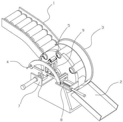
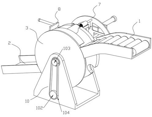
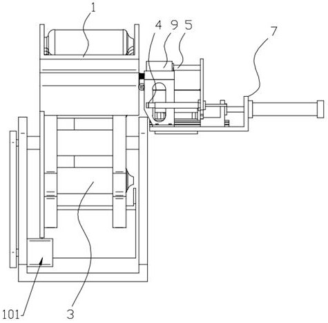
[0032] Such as Figure 1 to Figure 10 As shown, a small silencer steel pipe automatic press-fitting equipment includes a feeding mechanism 1, a discharge mechanism 2, a rotating mechanism 3, a detection mechanism 4, a coating mechanism 5, a pressing mechanism 6, a pressing mechanism 7 and a driving mechanism Mechanism 10, the feeding mechanism 1 and the discharging mechanism 2 are respectively arranged on the feeding end and the discharging end of the rotating mechanism 3 and are respectively used for feeding and discharging the products, and the rotating mechanism 3 is provided with a plurality of The placement groove 33 for placing the muffler body can perform step-by-step rotary motion under the action of the drive mechanism 10. The detection m...


PUM


Abstract

The invention discloses an automatic press-fitting equipment for small muffler steel pipes, relating to the field of automation equipment, including a feeding mechanism, a material discharging mechanism, a rotating mechanism, a detection mechanism, a coating mechanism, a pressing mechanism, a pressing power mechanism and a driving mechanism , the detection mechanism, the coating mechanism and the press-fit mechanism are all installed on the press-fit power mechanism and can move synchronously, so as to respectively realize the filter screen detection, flux coating and steel pipe press-fit operation of the muffler body, the present invention The rotating mechanism adopts a rotating feeding method, which significantly reduces the equipment footprint compared with the traditional linear production line. At the same time, the press-fitting power mechanism integrates a detection mechanism, a coating mechanism and a pressing mechanism. Three The process is carried out synchronously at three positions, which improves the consistency and accuracy of the production process. The feeding and discharging of the muffler are automatically realized by its gravity, and there is no need to set up related power devices, which simplifies the structural layout and reduces the cost of production. equipment cost.

Description

technical field [0001] The invention belongs to the field of automation equipment, and in particular relates to an automatic press-fitting equipment for small-sized muffler steel pipes. Background technique [0002] The traditional muffler includes a body, an air inlet pipe, an air outlet pipe, and a filter structure. At present, for the press-fitting process of the air inlet pipe or the air outlet pipe, semi-automatic press-fitting is mostly used, that is, manual loading and unloading are required, and the press-fitting Previously, it was necessary to manually detect the filter screen and apply flux to the press-fitting part of the device body, which was inefficient and had large installation errors. [0003] The Chinese Patent Publication No. CN107717404B also discloses an automatic press-fitting production line for small steel pipes for liquid reservoirs, which adopts a linear production line layout and occupies a large space, and the detection of the filter screen and th...

Claims


Application Information

Patent Timeline
Patent Type & Authority Patents(China)
IPC IPC(8): B23P19/00B23P19/027B05C1/02
CPCB05C1/02B23P19/001B23P19/027
Inventor 孙启田孔德超孔令荣左家秀佘金杰
Owner 芜湖文青机械设备设计有限公司
Why Eureka
Try Eureka