Centrifugal rotating spiral concentrator

A spiral concentrator and centrifugal separation technology, applied in the field of beneficiation, can solve the problems such as the large influence of material separation and layering effect parameters, the difficulty in ensuring the stability of the separation process, the low separation efficiency and the low processing, and the like. Sorting efficiency and effects of low processing, high integration and high sorting accuracy

Pending Publication Date: 2020-05-08
XIAN UNIV OF SCI & TECH
View PDF0 Cites 0 Cited by
  • Summary
  • Abstract
  • Description
  • Claims
  • Application Information

AI Technical Summary

Problems solved by technology

Although the structure of the spiral separator is simple and has no power, the separation efficiency and processing are relatively low; and the structure of the spiral separator is fixed without power input, so the separation process is fixed and the effect of material separation and stratification It is greatly affected by the parameters of the equipment itself, resulting in low sorting accuracy
[0003] The centrifugal concentrator uses the conical surface of the drum for centrifugal separation. It is easy to cause materials to be mixed on the same plane, and it is difficult to ensure the stability of the separation process. The separation of the centrifugal concentrator is a discontinuous separation. To achieve fine The selection can only be realized by adding additional equipment

Method used


Image

  • Centrifugal rotating spiral concentrator
  • Centrifugal rotating spiral concentrator
  • Centrifugal rotating spiral concentrator

Examples


Embodiment 1

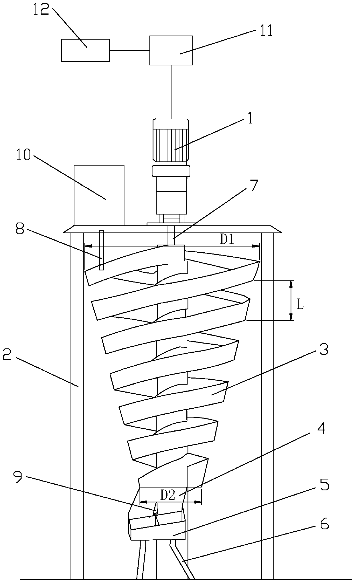
[0029] like figure 1 A centrifugal rotating spiral mineral concentrator shown includes a frame 2, a rotating main shaft 7, a feeding box 10, a spiral centrifugal separation tank 3, a reduction motor 1, a frequency converter 11, a controller 12 and a multi-product receiving mechanism, The rotating main shaft 7 is vertically installed in the frame 2 along the central axis of the frame 2, the upper end of the rotating main shaft 7 is connected with the top center of the frame 2 in rotation, and the lower end of the rotating main shaft 7 is connected with the bottom of the frame 2. The center of the bottom is rotationally connected, the spiral centrifugal separation tank 3 is fixedly installed on the outer wall of the rotating main shaft 7, the feed box 10 is arranged on the top side of the frame 2, and the bottom of the feed box 10 is provided with a Give the feed port 8 of the spiral centrifugal separation tank 3 feeding, the lower end of the feed port 8 is located at the feed i...

Embodiment 2

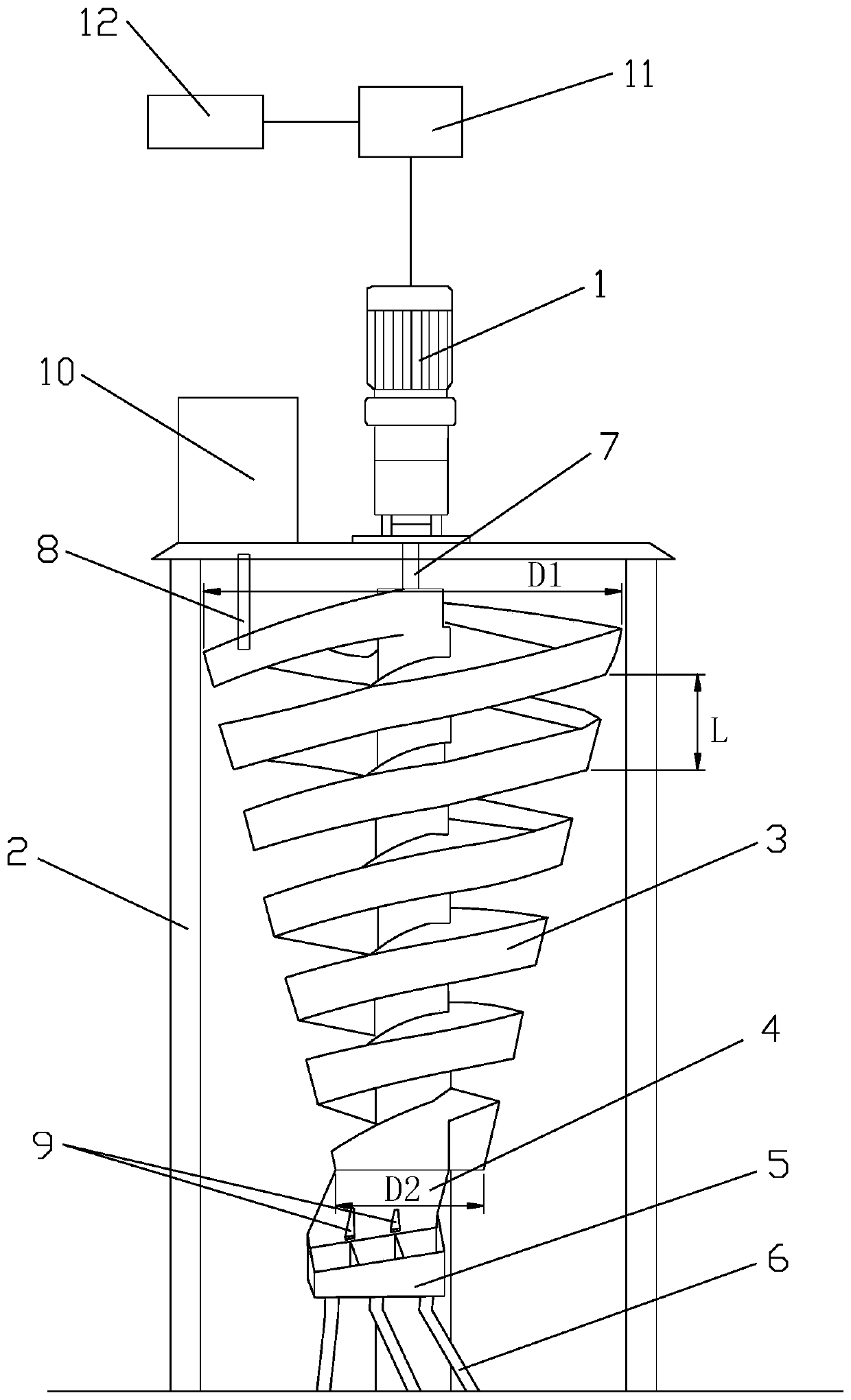
[0042] like figure 2 As shown, the difference between this embodiment and Embodiment 1 is that the number of the distribution grids 9 is two, the number of notches in the receiving trough 5 and the number of discharge pipes 6 are three. Two distribution grids 9 can divide the distribution chute 4 into three distribution troughs; correspondingly, the number of notches in the receiving chute 5 and the number of discharge pipes 6 are three, each receiving material The notches in the tank 5 correspond to a distribution tank and a discharge pipe 6 respectively. Three distribution grids 9 are used to separate materials of different densities, and three products of different densities can be produced, namely light products, heavy products and mid product. The kind of sorting product is determined by the number of material distribution grids 9 . The lower ends of the three discharge pipes 6 can respectively extend into three ring-shaped hoppers to collect materials. The three ring-...


PUM


Abstract

The invention discloses a centrifugal rotating spiral concentrator which comprises a rack, a rotating spindle, a feed box, a spiral centrifugal classifying tank, a gear motor, a frequency converter, acontroller and a multi-product receiving mechanism. The rotating spindle is vertically mounted in the rack along the center axis of the rack. The spiral centrifugal classifying tank is fixedly mounted on the outer wall of the rotating main shaft. The feed box is arranged on one side of the rack. A feed opening is formed in the bottom of the feed box. The gear motor is mounted on the outer side ofthe top of the rack. An output shaft of the gear motor is fixedly connected with the upper end of the rotating spindle. The gear motor is connected with the frequency converter. The frequency converter is connected with the controller. The multi-product receiving mechanism is arranged at the lower end of the spiral centrifugal classifying tank and can collect materials of different densities obtained after classifying. The outline of the spiral centrifugal classifying tank is in an inverted circular table shape, and the diameter of the spiral centrifugal classifying tank is gradually reducedfrom top to bottom. The centrifugal rotating spiral concentrator is simple in structure, high in sorting efficiency and high in adaptability, classifying equipment is convenient to operate, and the technological process is simple.

Description

technical field [0001] The invention belongs to the technical field of mineral processing, and in particular relates to a centrifugal rotating spiral mineral processing machine with a gradually changing diameter of a spiral chute. Background technique [0002] Spiral separator and centrifugal concentrator are two kinds of equipment commonly used in the mineral processing and separation process. During the separation process of the spiral separator, the ore pulp naturally swirls from high to low, and an inertial centrifugal force is generated in the rotating inclined plane flow velocity. According to the difference in specific gravity, particle size and shape of minerals, the light products are separated from the heavy products through the action of gravity and centrifugal force of the swirling flow. Although the structure of the spiral separator is simple and has no power, the separation efficiency and processing are relatively low; and the structure of the spiral separator ...

Claims


Application Information

Patent Timeline
Patent Type & Authority Applications(China)
IPC IPC(8): B03B5/52B03B13/00
CPCB03B5/52B03B13/00
Inventor 于伟刘莉君
Owner XIAN UNIV OF SCI & TECH
Why Eureka
Try Eureka