Automatic smearing device for blood smear manufacturing
A blood smear and transmission device technology, which is applied to measurement devices, preparation and sampling of samples for testing, can solve the problems of uneven blood smearing, low work efficiency, wasting time, etc., and avoid uneven blood smearing and work. Efficient effect
- Summary
- Abstract
- Description
- Claims
- Application Information
AI Technical Summary
Problems solved by technology
Method used
Image
Examples
Embodiment 1
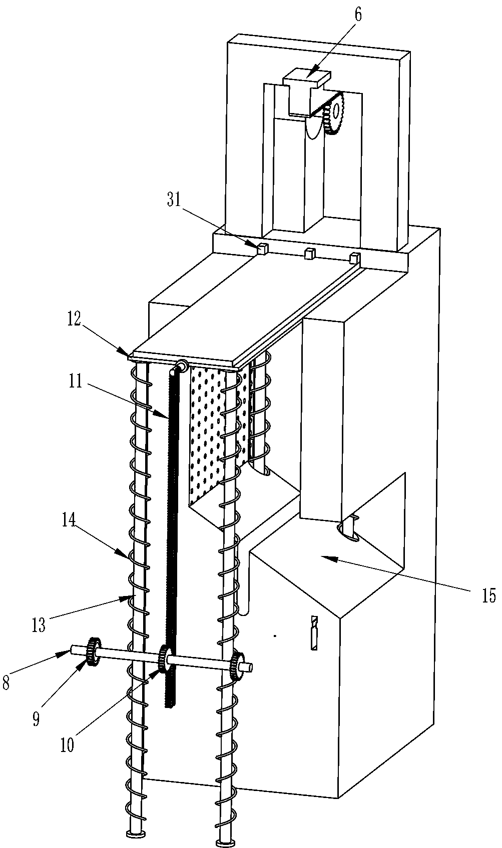
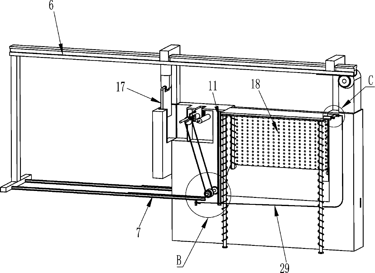
[0024] see figure 1 , figure 2 , image 3 , Figure 5 , Image 6 with Figure 7 , an automatic smear device for making blood smears, including a support frame 1, a cabinet 2, a lower hopper 3, a smear mechanism and a moving mechanism, the top of the support frame 1 is fixedly connected to the organic case 2, and the front middle of the case 2 is provided with a diagonal Groove 15, a lower hopper 3 is installed in the middle of the lower part of the outer front side of the cabinet 2, the lower hopper 3 cooperates with the chute 15, and the upper part of the cabinet 2 is provided with a moving mechanism that can place the glass slide, and the moving mechanism cooperates with the chute 15, the cabinet 2. The upper part is provided with a smearing mechanism, and the smearing mechanism cooperates with the moving mechanism. The front and rear sides of the inner upper part of the cabinet 2 are provided with air outlets 18.
[0025] The smearing mechanism includes a motor 4, a f...
Embodiment 2
[0031] see image 3 , Figure 4 , Figure 5 with Figure 7 Compared with Embodiment 1, the main difference of this embodiment is that in this embodiment, a first transmission device 19, a brush wheel 20, a second transmission device 21, a third gear 22, a slanting block 23, and a second spring 24 are also included. , push rod 25, water spray pipe 26 and piston 27, the rotating type between the upper left side in the cabinet 2 is provided with a brush wheel 20, and a first brush wheel 20 is provided between the left side brush wheel 20 front and the rotating shaft 8 front. Transmission device 19, a second transmission device 21 is arranged between the left side brush wheel 20 front part and the left side upper part of the front side of the cabinet 2, the second transmission device 21 rear side right part circle center position and the right side brush wheel 20 front part are both The third gear 22 is fixedly connected, and the third gears 22 on the left and right sides are m...
Embodiment 3
[0034] see figure 2 , Figure 5 , Image 6 , Figure 7 with Figure 8 Compared with Embodiment 1 and Embodiment 2, the main difference of this embodiment is that in this embodiment, a touch dryer 28 and a button switch 281 are also included, and a touch dryer 28 is installed on the upper left side of the cabinet 2 , The push piece 17 is located in the touch dryer 28 , and the upper parts of the front and rear sides of the touch dryer 28 are equipped with a button switch 281 , and the button switch 281 has a circuit connection with the touch dryer 28 .
[0035] Also include stay cord 29, fixed rod 30, clamping rod 31 and the 3rd spring 32, casing 2 upper right side sliding type is provided with clamping rod 31, and clamping rod 31 right side is connected between front and rear sides and cabinet 2 inner sides. There is a third spring 32, a pull cord 29 is connected to the middle part of the right side of the clamping rod 31, a fixed rod 30 is fixedly connected to the right ...
PUM
 Abstract
Description
Claims
Application Information
 - R&D Engineer
- R&D Manager
- IP Professional
- Industry Leading Data Capabilities
- Powerful AI technology
- Patent DNA Extraction
Browse by: Latest US Patents, China's latest patents, Technical Efficacy Thesaurus, Application Domain, Technology Topic, Popular Technical Reports.
© 2024 PatSnap. All rights reserved.Legal|Privacy policy|Modern Slavery Act Transparency Statement|Sitemap|About US| Contact US: help@patsnap.com


