Efficient forage chopping machine for livestock breeding
A shredder and high-efficiency technology, which is applied in the field of high-efficiency forage shredders for livestock feeding, can solve problems such as heavy labor, uneven dryness and wetness of forage, and low work efficiency, so as to achieve simple and convenient adjustment, improve the shredding effect, Effect of improving humidity uniformity
- Summary
- Abstract
- Description
- Claims
- Application Information
AI Technical Summary
Problems solved by technology
Method used
Image
Examples
Embodiment 1
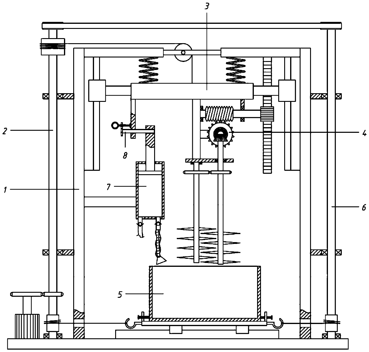
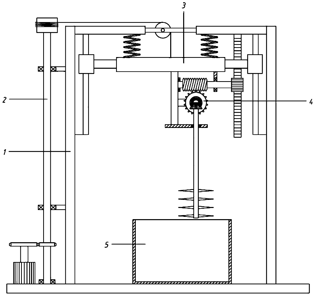
[0064] A high-efficiency forage chopper for livestock feeding, comprising a frame 1, a driving component 2, a lifting component 3, a chopping component 4 and a chopping box 5;
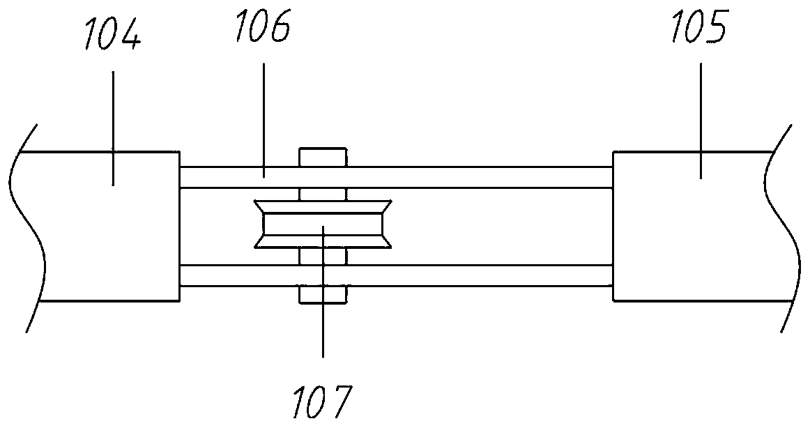
[0065] The frame 1 includes a base 101, a left side plate 102, a right side plate 103, a left support plate 104, a right support plate 105, a mounting plate 106 and a guide wheel 107, and the left side plate 102 and the right side plate 103 are symmetrically fixed on the base 101 , the top of the left side plate 102 is connected to the right with a left support plate 104, the top plate of the right side plate 103 is connected with a right support plate 105 to the left, and an interval mounting plate 106 is connected between the left support plate 104 and the right support plate 105, and the mounting plate Lead wheel 107 is housed between 106;
[0066] The left side of the frame 1 is provided with a driving assembly 2; the upper part of the frame 1 is provided with a lifting assembly 3; the lower part o...
Embodiment 2
[0068] A high-efficiency forage chopper for livestock feeding, comprising a frame 1, a driving component 2, a lifting component 3, a chopping component 4 and a chopping box 5;
[0069] The frame 1 includes a base 101, a left side plate 102, a right side plate 103, a left support plate 104, a right support plate 105, a mounting plate 106 and a guide wheel 107, and the left side plate 102 and the right side plate 103 are symmetrically fixed on the base 101 , the top of the left side plate 102 is connected to the right with a left support plate 104, the top plate of the right side plate 103 is connected with a right support plate 105 to the left, and an interval mounting plate 106 is connected between the left support plate 104 and the right support plate 105, and the mounting plate Lead wheel 107 is housed between 106;
[0070] The left side of the frame 1 is provided with a driving assembly 2; the upper part of the frame 1 is provided with a lifting assembly 3; the lower part o...
Embodiment 3
[0082] On the basis of embodiment 2,
[0083] The chopping assembly 4 also includes a third gear 415, a fourth gear 414 and a third rotating shaft 416;
[0084] No. 4 gear 414 is also housed on No. 2 rotating shaft 411, and No. 4 gear 414 is positioned at below transverse plate 412; 416 top and transverse plate 412 are rotatably connected by bearing; No. 3 rotating shaft 416 lower segment also is equipped with cutting knife 413;
[0085]Specifically, while the second rotating shaft 411 rotates, the third rotating shaft 416 is also rotated through gear transmission. Since the two shafts turn in opposite directions, a crushing effect is formed between them, thereby improving the chopping effect of the cutting knife 413.
PUM
 Abstract
Description
Claims
Application Information
 - R&D
- Intellectual Property
- Life Sciences
- Materials
- Tech Scout
- Unparalleled Data Quality
- Higher Quality Content
- 60% Fewer Hallucinations
Browse by: Latest US Patents, China's latest patents, Technical Efficacy Thesaurus, Application Domain, Technology Topic, Popular Technical Reports.
© 2025 PatSnap. All rights reserved.Legal|Privacy policy|Modern Slavery Act Transparency Statement|Sitemap|About US| Contact US: help@patsnap.com


