
Traction inverter main loop for permanent magnet synchronous traction system

A traction inverter and traction system technology, applied in the electrical field, can solve problems such as drive motor stop and rail vehicle power drop

Pending Publication Date: 2020-05-01
CRRC XIAN YONGEJIETONG ELECTRIC CO LTD
View PDF0 Cites 0 Cited by
  • Summary
  • Abstract
  • Description
  • Claims
  • Application Information

AI Technical Summary

Problems solved by technology

[0005] The invention provides a traction inverter main circuit for a permanent magnet synchronous traction system to solve the technical problem in the prior art that a problem in the inverter circuit will cause all the drive motors to stop working, thereby causing a significant drop in the power of the rail vehicle

Method used


Image

  • Traction inverter main loop for permanent magnet synchronous traction system
  • Traction inverter main loop for permanent magnet synchronous traction system
  • Traction inverter main loop for permanent magnet synchronous traction system

Examples


Embodiment Construction

[0023] In order to make the purpose, technical solutions and advantages of the present invention clearer, the technical solutions in the embodiments of the present invention will be clearly and completely described below in conjunction with the accompanying drawings in the embodiments of the present invention. Obviously, the described embodiments are the Some, but not all, embodiments are invented. Based on the embodiments of the present invention, all other embodiments obtained by persons of ordinary skill in the art without making creative efforts belong to the protection scope of the present invention.

[0024] The power traction system of rail vehicles can generally be divided into asynchronous traction system and permanent magnet synchronous traction system. The difference between the two is whether the type of driving motor is an asynchronous motor or a synchronous motor. characteristics, in line with the development needs of national conservation and low-carbon economy,...


PUM


Abstract

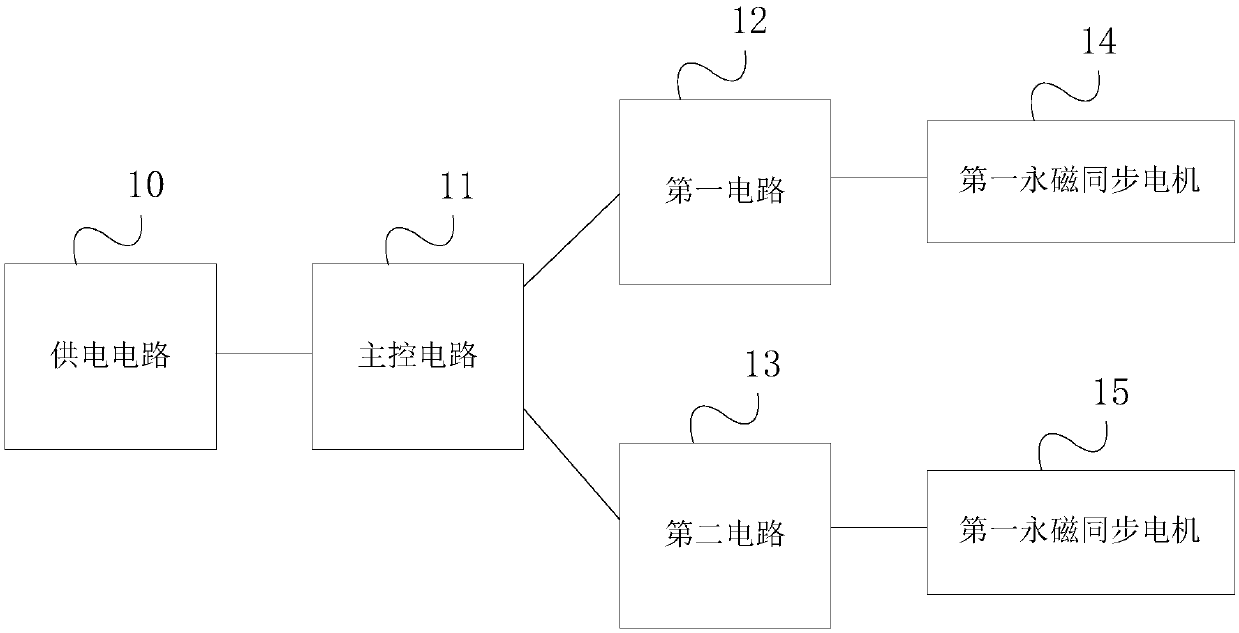
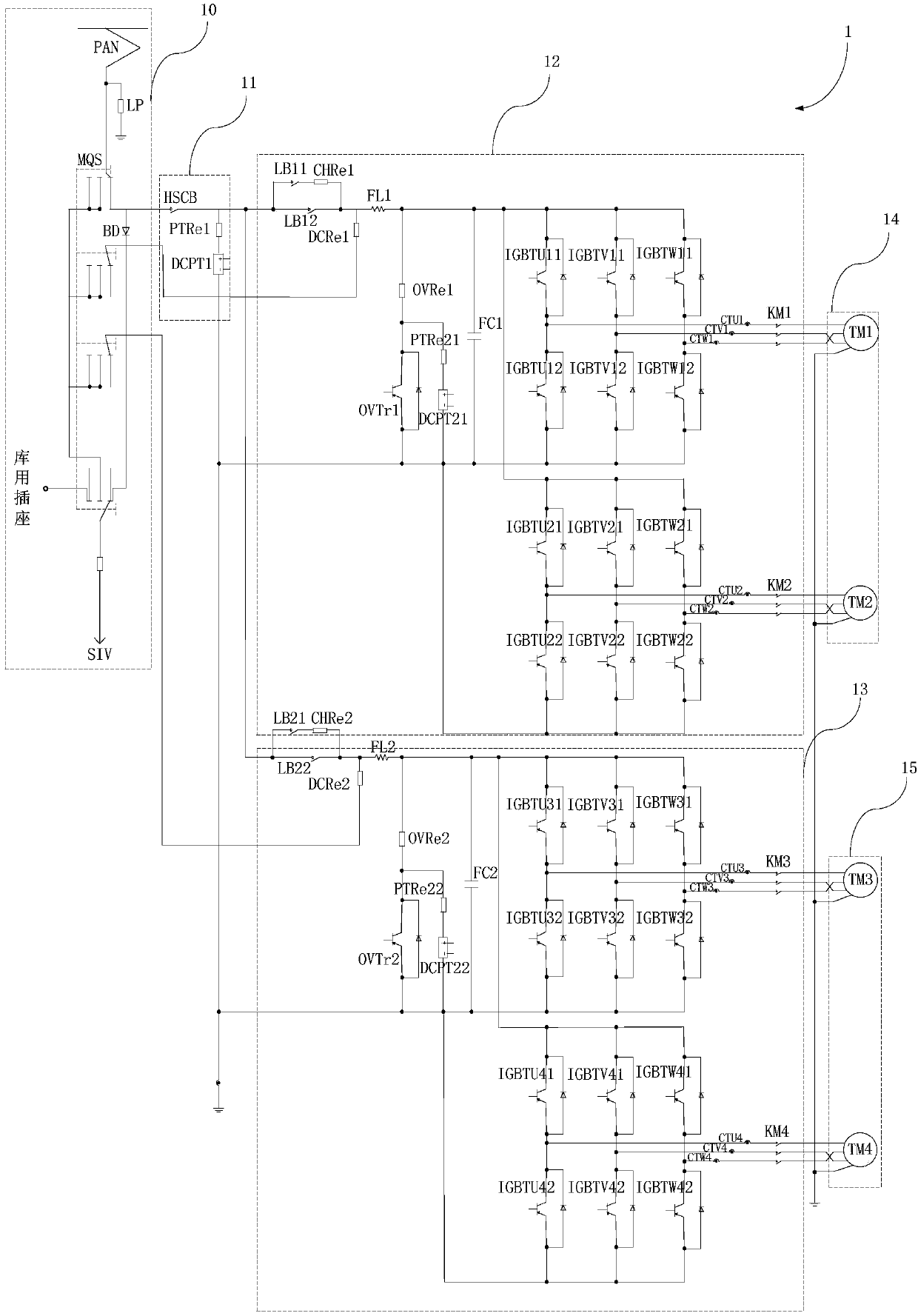
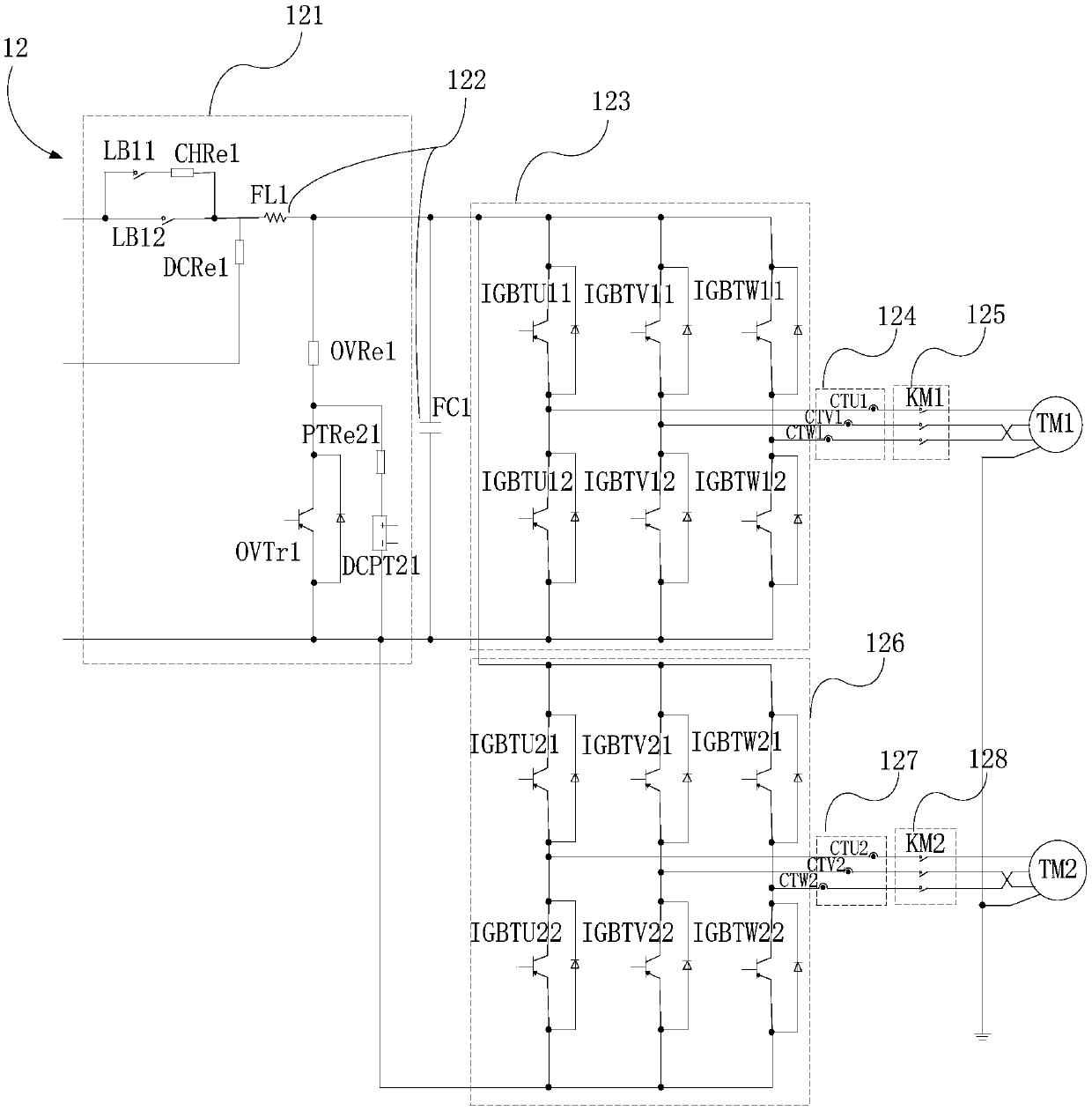
The invention provides a traction inverter main loop for a permanent magnet synchronous traction system, which comprises a power supply circuit, a main control circuit, a first circuit and a second circuit, wherein the power supply circuit is connected with one end of the main control circuit, the other end of the main control circuit is connected with the first circuit and the second circuit respectively, the first circuit and the second circuit are connected in parallel, the first circuit is connected with the two first permanent magnet synchronous motors respectively, and the second circuitis connected with the two second permanent magnet synchronous motors respectively; when the main control circuit detects that the power supply of the power supply circuit is abnormal, the main control circuit controls the power supply circuit to be disconnected with the first circuit and the second circuit; when the first circuit breaks down, the first circuit can be disconnected with the main control circuit, or when the second circuit breaks down, the second circuit can be disconnected with the main control circuit. The motor is driven by the first circuit and the second circuit respectively, so that the problem that faults cannot be eliminated in time when the motor is driven by a single circuit is avoided, and the fault running capability and stability of the vehicle are improved.

Description

technical field [0001] The invention relates to the electrical field, in particular to a traction inverter main circuit for a permanent magnet synchronous traction system. Background technique [0002] As a means of urban transportation, rail vehicles are responsible for more and more transportation needs. Among them, the power system of rail vehicles is generally a power traction system. The traction system provides the required power and braking force for the train to ensure the normal operation of the vehicle. [0003] At present, most of the power traction systems use the asynchronous motor traction system, which uses the asynchronous motor as the power source. In view of the characteristics of the asynchronous motor, the main circuit generally adopts the vehicle control mode of 1C (Converter) 4M (Motor), that is, a The inverter unit controls 4 traction motors. The inverter unit is composed of IGBT (Insulated Gate Bipolar Transistor) components. The 1C4M vehicle control ...

Claims


Application Information

Patent Timeline
IPC IPC(8): B60L15/20B60L3/00H02P6/04H02P27/06
CPCB60L3/0023B60L15/20B60L2200/26B60L2220/14B60L2220/42H02P6/04H02P27/06Y02T10/64Y02T10/72
Inventor 宁波张彩霞王艳伍
Owner CRRC XIAN YONGEJIETONG ELECTRIC CO LTD
Learn More