
Composite-structure wind driven generator and power generation system

A technology for wind turbines and composite structures, which is applied in wind power generation, magnetic circuit shape/pattern/structure, and winding conductor shape/pattern/structure, etc., can solve problems such as hindering grid voltage recovery, and improve power density and power generation. Efficiency, safety improvement, effect of reducing excitation current

Active Publication Date: 2020-11-27
QILU UNIV OF TECH
View PDF9 Cites 0 Cited by
  • Summary
  • Abstract
  • Description
  • Claims
  • Application Information

AI Technical Summary

Problems solved by technology

When a bidirectional converter is used for grid-connected operation, it is necessary to absorb reactive power from the grid, especially when the grid fails, absorbing reactive power from the grid will further hinder the recovery of the grid voltage

Method used


Image

  • Composite-structure wind driven generator and power generation system
  • Composite-structure wind driven generator and power generation system
  • Composite-structure wind driven generator and power generation system

Examples


Embodiment 1

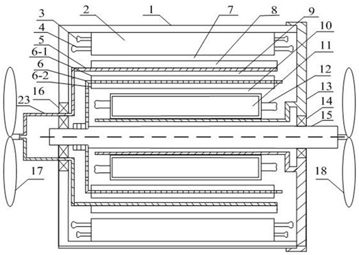
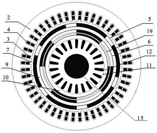
[0033] like Figure 1-2 As shown, a wind power generator with a composite structure includes a casing 1, one side of the casing 1 is fixedly provided with an end cover 13, and the end cover 13 is a part of the casing 1, and the casing 1 is rotatable A rotating shaft 15 is connected, and one end of the rotating shaft 15 is fixedly connected with a second wind turbine 18, and one end of the rotating shaft 15 connected to the second wind turbine 18 is rotationally connected with the end cover 13 through the first bearing 14, and in the casing 1, The outer side of the rotating shaft 15 is provided with an inner stator 11 , a permanent magnet rotor 6 , a magnetic ring rotor 5 and an outer stator 2 in sequence.

[0034] Between the outer stator 2 and the magnetic ring rotor 5 is the first air gap 7, between the magnetic ring rotor 5 and the permanent magnet rotor 6 is the second air gap 9, the permanent magnetic rotor 6 and the inner stator Between 11 is the third air gap 10 .

[...

Embodiment 2

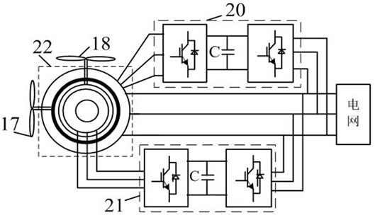
[0045] like Figure 1-3 As shown, a power generation system using a composite structure wind generator includes a composite structure wind generator 22 , an external brushless doubly-fed generator bidirectional converter 20 and an internal permanent magnet generator bidirectional converter 21 .

[0046]The composite structure wind power generator 22 includes a casing 1, one side of the casing 1 is fixedly provided with an end cover 13, the end cover 13 is a part of the casing 1, and the casing 1 is rotatably connected with a rotating shaft 15. One end of the rotating shaft 15 is fixedly connected to the second wind turbine 18, and one end of the rotating shaft 15 connected to the second wind turbine 18 is rotationally connected to the end cover 13 through the first bearing 14. In the casing 1, the rotating shaft The outer side of 15 is provided with an inner stator 11, a permanent magnet rotor 6, a magnetic ring rotor 5 and an outer stator 2 in sequence.

[0047] Between the ...


PUM


Abstract

The invention discloses a composite-structure wind driven generator and a power generation system. The power generation system comprises a wind driven generator of a composite structure, a bidirectional converter of an external brushless doubly-fed generator, and a bidirectional converter of internal permanent magnet generator, wherein a power winding of the composite structure wind driven generator is connected with a power grid, a control winding of the composite structure wind driven generator is connected with the power grid through an outer brushless doubly-fed generator bidirectional converter, and an inner stator winding of the composite structure wind driven generator is connected with the power grid through an inner permanent magnet generator bidirectional converter. The advantages of a permanent magnet generator and a brushless doubly-fed generator are combined, the power density of the generator and the power generation capacity of a single machine are improved, and continuous and safe operation in the power grid fault period is ensured.

Description

technical field [0001] The invention relates to the technical field of wind power generation equipment, in particular to a wind power generator with a composite structure and a power generation system. Background technique [0002] Wind energy is a kind of clean renewable energy. In recent years, it has received extensive attention in the field of power generation at home and abroad. my country has abundant wind energy reserves, which makes the large-scale development of wind power generation possible. [0003] The permanent magnet generator is a generator that is excited by a permanent magnet to generate a rotating magnetic field. The permanent magnet acts as a rotor to generate a rotating magnetic field. The three-phase stator winding reacts through the armature under the action of the rotating magnetic field to induce a three-phase symmetrical current. Due to the characteristics of high power generation efficiency, permanent magnet generators have been widely used in the ...

Claims


Application Information

Patent Timeline
Patent Type & Authority Applications(China)
IPC IPC(8): H02K16/00H02K1/30H02K3/16H02J3/38
CPCH02K16/00H02K1/30H02K3/16H02J3/38H02J2300/28Y02E10/72
Inventor 刁统山严志国张绍杰张金烽
Owner QILU UNIV OF TECH
Learn More