
Water-gas separator

A technology of water-gas separator and separator, applied in the direction of separation method, liquid degassing, chemical instrument and method, etc., can solve the problem of CO concentration exceeding the standard, and achieve the effect of easy separation

Inactive Publication Date: 2020-05-01
李红良
View PDF6 Cites 0 Cited by
  • Summary
  • Abstract
  • Description
  • Claims
  • Application Information

AI Technical Summary

Problems solved by technology

[0003] In view of this, the object of the present invention is to provide a water-gas separator, which aims to overcome the defect that the CO concentration in the existing circulating water exceeds the standard

Method used


Image

  • Water-gas separator
  • Water-gas separator
  • Water-gas separator

Examples


Embodiment 1

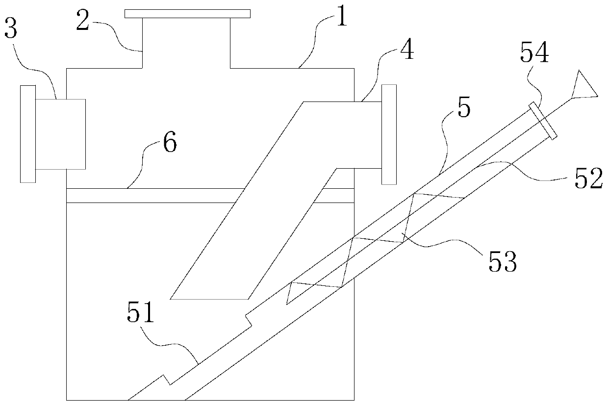
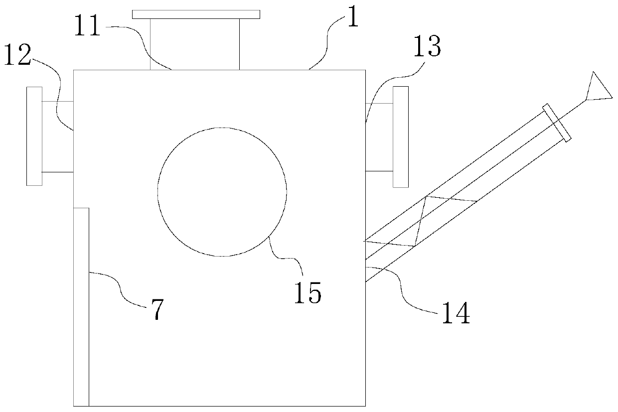
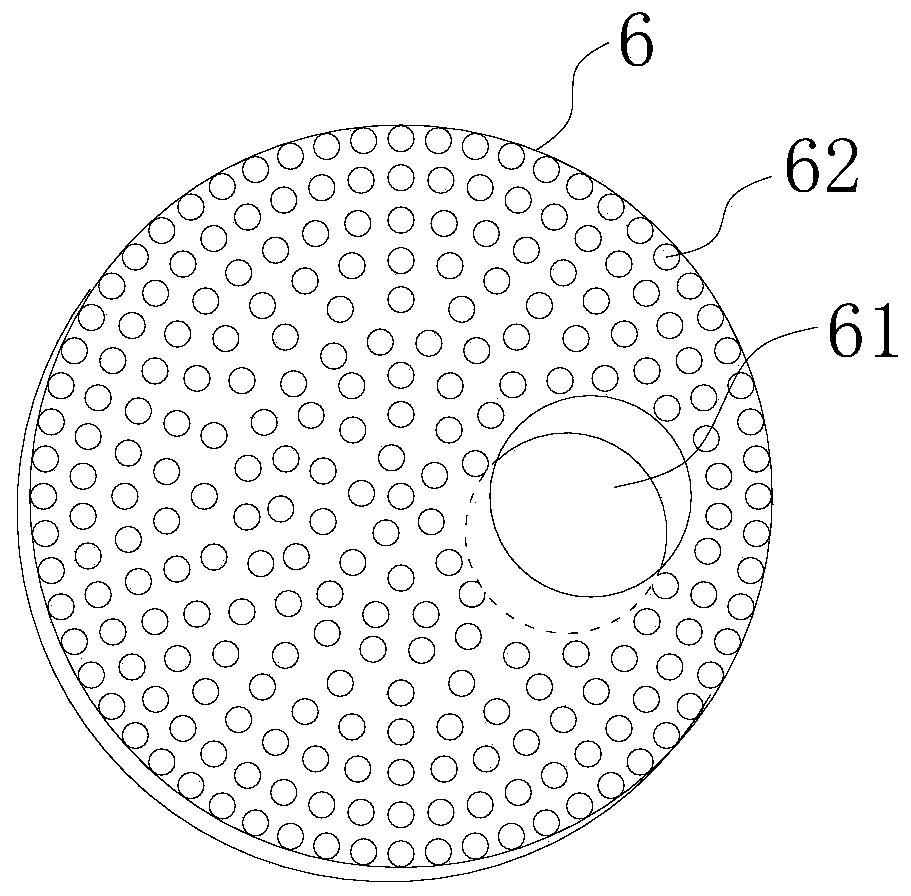
[0017] like Figure 1-3 As shown, a water-gas separator includes a housing 1, the top of the housing 1 is provided with an exhaust port 11, and the exhaust port 11 is provided with an exhaust pipe 2, and the separated gas is exhausted The pipe 2 is connected to the flue for centralized treatment. One side of the housing 1 is provided with a water inlet 12, and the other side is provided with a water outlet 13 and a slag discharge outlet 14, and the water inlet 12 and the water outlet 13 are at the same height. The slag discharge port 14 is located below the water outlet 13. The water inlet 12 and the water outlet 13 are respectively provided with a water inlet pipe 3 and a water outlet pipe 4. The water outlet pipe 4 extends to the lower end of the housing 1 and is inclined downward. Set to prevent the gas from leaking directly into the sedimentation tank when the water level of the separator is low. The slag discharge port 14 is provided with a slag discharge pipe 5 for distu...

Embodiment 2

[0019] Based on the structure of Embodiment 1, in Embodiment 2, an observation hole 15 is provided on the housing 1 to facilitate observation of the sedimentation condition of the separator.

Embodiment 3

[0021] Based on the structure of Embodiment 1, in Embodiment 3, an online CO detector is provided at the water outlet 13, which can monitor the CO concentration of the water in the outlet pipe 4 in real time.


PUM


Abstract

The invention discloses a water-gas separator. The water-gas separator comprises a shell, wherein a gas discharging opening is arranged at the top part of the shell; a gas discharging pipe is arrangedon the gas discharging opening; a water inlet is arranged at one side of the shell; a water outlet and a slag discharging opening are arranged at the other side of the shell; the water inlet and thewater outlet are positioned at the same height; the slag discharging opening is positioned below the water outlet; a water inlet pipe and a water outlet pipe are respectively arranged on the water inlet and the water outlet; the water outlet pipe extends to the lower end part of the interior of the shell and is obliquely arranged downwards; gas is prevented from being directly introduced into a sedimentation tank to leak out when the water level of the separator is low; a slag discharging pipe is arranged in the slag discharging opening; the deslagging pipe is obliquely arranged on the shell and located below the water outlet pipe; an opening is arranged at a position, right opposite to a pipe opening of the water outlet pipe, of the slag discharging pipe; a stirring shaft is arranged in the slag discharging pipe; stirring blades are arranged at the outer side of the stirring shaft; a rubber pipe cover matched with the slag discharging pipe is arranged on the stirring shaft; and a circular water-gas separation plate is fixedly arranged below the water inlet of the interior of the shell. The water-gas separator provided by the invention is good in CO and water separation effect, lowin cost, high in safety benefit and easy to operate and maintain.

Description

technical field [0001] The invention relates to the technical field of water-gas separation, in particular to a water-gas separator. Background technique [0002] The heat source of the raw material preheating system of our company Shanxi Taigang Xinlei Resources Co., Ltd. is the waste heat of the rotary kiln, which contains a large amount of CO and dust. The dust removal system at the end of the preheating system is water dust removal. In order to save water, the water of water dust removal is precipitated. Recycling, the recycled water contains a lot of CO, which is easy to cause poisoning incidents. In the initial stage of project completion, testing was carried out around the water dedusting system, and the CO concentration once exceeded 500PPM, which may cause safety accidents at any time. Contents of the invention [0003] In view of this, the object of the present invention is to provide a water-gas separator aimed at overcoming the defect of excessive CO concentra...

Claims


Application Information

Patent Timeline
Patent Type & Authority Applications(China)
IPC IPC(8): B01D19/00
CPCB01D19/00
Inventor 贾明魏建恩赵国成
Owner 李红良
Learn More