
Fault positioning method and system for spliced image floor defect detection

A defect detection and fault location technology, applied in the field of defect detection, can solve problems such as difficult positioning

Pending Publication Date: 2020-04-28
中国烟草总公司北京市公司
View PDF0 Cites 6 Cited by
  • Summary
  • Abstract
  • Description
  • Claims
  • Application Information

AI Technical Summary

Problems solved by technology

In actual operation, due to the uncertainty of the position and angle of each shooting lens, the position and order of the same position on the floor in the picture sequence have certain differences, which brings certain difficulties to the positioning of defects.

Method used


Image

  • Fault positioning method and system for spliced image floor defect detection
  • Fault positioning method and system for spliced image floor defect detection
  • Fault positioning method and system for spliced image floor defect detection

Examples


Embodiment 1

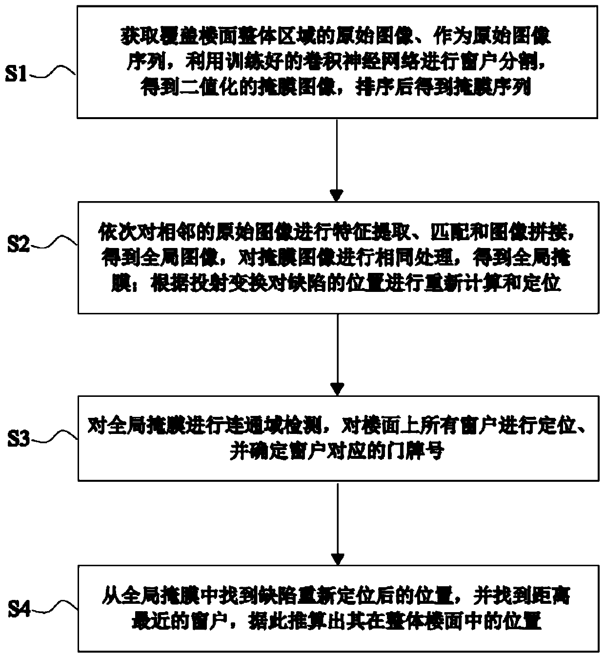
[0071] Such as figure 1 As shown, this embodiment 1 provides a fault location method for splicing image floor defect detection, including the following steps:

[0072] S1: Window segmentation: First, use the trained Mask RCNN to segment the windows in each original image I in the original image sequence to obtain a binarized mask image I with the same size as the original image mask , where 0 represents a window, and 255 represents a non-window; according to the original image sequence {I mask} in the order of each original image, sort the mask images, and get the mask sequence

[0073] S2: Image stitching: Since the two adjacent photos are also adjacent in spatial position when shooting, all the original images in the original image sequence are searched for feature points and stitched to obtain the global image G, and the mask sequence All mask images of the same splicing process are performed to obtain the global mask G mask , and at the same time relocate the defect pos...

Embodiment 2

[0101] Such as figure 2 As shown, this embodiment 2 provides a fault location system for fault detection of spliced ​​image floor defect detection by running the method provided by embodiment 1, including a window segmentation module 1, an image splicing module 2, a window positioning module 3 and a defect location module connected in sequence. Positioning module 4, the window division module 1 is configured to:

[0102] Obtain a series of original images covering the entire area of ​​the floor as an original image sequence, use the trained convolutional neural network to segment the windows in each original image, and obtain a binarized mask with the same size as the original image image, and sort all the mask images to get the mask sequence;

[0103] Image stitching module 2 is configured as:

[0104] Perform feature extraction, matching and image stitching on adjacent original images in turn to obtain a global image; use the same method to perform feature extraction, mat...


PUM


Abstract

The invention provides a fault positioning method and a corresponding system for spliced image floor defect detection. The method mainly comprises the steps of window segmentation, image splicing, window positioning and defect positioning. According to the method, firstly, collected floor image sequences are spliced, feature extraction and geometric correction are carried out on a floor area, thecorresponding relation of pixels in a shot image in a reference floor coordinate system is obtained, and therefore defects output by an automatic defect recognition algorithm are accurately positioned. According to the method, the problem that the sequence and the position of the same area of the floor in the picture sequence are different due to the uncertainty of the position and the angle of the lens shot each time can be effectively solved; in the process of floor defect detection through the spliced images, the defect positioning precision can be remarkably improved, the reliability of the positioning result is high, and the method is suitable for being applied and popularized in floor defect detection and maintenance work.

Description

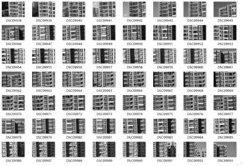
technical field [0001] The invention belongs to the technical field of defect detection, and in particular relates to a fault location method and system for splicing image floor defect detection. Background technique [0002] After long-term exposure to the sun, wind or rain and snow erosion, the exterior walls of buildings will gradually appear falling, broken and even cracked exterior walls. The detection of these faults and defects based on photography is accurate and economical. , Efficient advantages. However, in actual operation, it is often necessary to shoot the floor from a relatively long distance (greater than 50 meters). In order to reduce geometric distortion and improve image resolution, a telephoto lens of more than 200 mm is required. Due to the limited angle of view of the telephoto lens, each image only covers a partial area of ​​the floor. In actual operation, due to the uncertainty of the position and angle of each shooting lens, the position and order ...

Claims


Application Information

Patent Timeline
Patent Type & Authority Applications(China)
IPC IPC(8): G06T7/00G06T7/10G06T7/187G06T7/70G06T3/40
CPCG06T3/4038G06T7/0002G06T7/10G06T7/187G06T7/70G06T2207/10016G06T2207/20021G06T2207/20081G06T2207/20084
Inventor 李冰谢刚王宇吴殿波陈福庭曹阳陈利吴晓
Owner 中国烟草总公司北京市公司
Learn More