Energy-saving and environment-friendly heat-dissipating device

A heat-dissipating device, energy-saving and environment-friendly technology, applied in preheating, steam superheating, feed water heaters, etc., can solve the problems of heat loss, unstable power generation, waste of resources, etc., and achieve the effect of improving efficiency, reducing heat loss and reducing waste.

Pending Publication Date: 2020-04-28
深圳华文网教育科技有限公司
View PDF3 Cites 2 Cited by
  • Summary
  • Abstract
  • Description
  • Claims
  • Application Information

AI Technical Summary

Problems solved by technology

However, although the flue gas discharged from boilers in the prior art has a low sulfur dioxide content, it still contains a large amount of heat, which is lost in the air, which not only causes the temperature of the surrounding environment to rise, destroys the ecological balance, but also is a resource waste of
[0004] On the other hand, in the existing technology, it is almost true how to use and recover the heat in the fuel furnace as much as possible, but considering the technical limitations and heat absorption characteristics, so the improvement of energy absorption is limited, and it does not reflect heating at present. The relationship between the fuel and the temperature in the exhaust pipe. In fact, if the fuel or air is not reasonable enough, it will lead to insufficient combustion or unstable power generation
[0005] However, for the problems in related technologies, no effective solutions have been proposed

Method used


Image

  • Energy-saving and environment-friendly heat-dissipating device
  • Energy-saving and environment-friendly heat-dissipating device
  • Energy-saving and environment-friendly heat-dissipating device

Examples


Embodiment 1

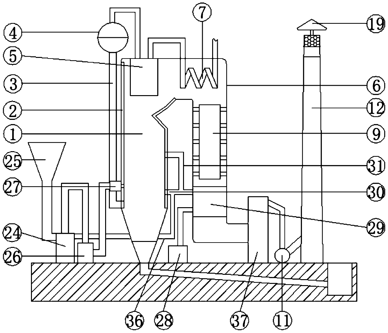
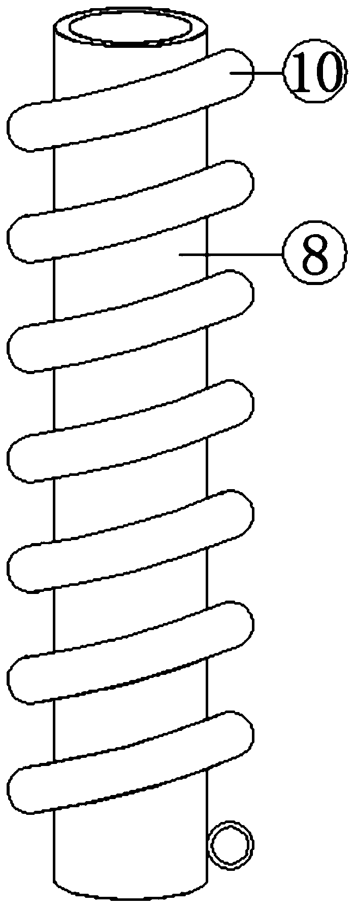
[0041] see Figure 1-8 , according to an embodiment of the present invention, an energy-saving and environment-friendly heat dissipation device includes a furnace body 1, a feeding device is provided on one side of the furnace body 1, a water-cooled wall 2 is fixed on the inner wall of the furnace body 1, and a water-cooled wall 2 is fixed on the inner wall of the furnace body 1. The outer wall of one side is fixed with a downcomer 3, the upper end of the downcomer 3 is fixed with a steam drum 4, the inner wall of the upper end of the furnace body 1 is fixed with a primary superheater 5, and the upper end of the furnace body 1 is fixed with a row A smoke pipe 6, the smoke exhaust pipe 6 has a Z-shaped structure, the inner wall of the upper end of the smoke exhaust pipe 6 is fixed with a secondary superheater 7, and the middle part of the smoke exhaust pipe 6 is provided with a preheating device, and the preheating device Including an inner cylinder 8, the outer wall of the inn...

Embodiment 2

[0045] see figure 1 , for the feeding device, the feeding device includes a coal mill 24, a feeder 25, a pulverizer 26 and a burner 27, and the input end of the coal mill 24 is fixedly provided with a feeder 25, so The output end of the coal mill 24 is connected with the input end of the pulverizer 26 through a conduit, and the output end of the pulverizer 26 is connected with the input end of the burner 27 through a conduit, and the burner 27 is fixedly embedded in the side wall of the furnace body 1 and the output end of the burner 27 protrudes into the furnace body 1 .

[0046] Through the above scheme of the present invention, the coal fed by the feeder 25 can be pulverized by the coal mill 24, and then injected into the body of furnace 1 through the pulverizer 26 and the burner 27 for combustion, so that the coal can be Burn more fully.

Embodiment 3

[0048] see figure 1 , 5 and 6, for the air supply device, the air supply device includes a blower 28, an air preheating device 29, a primary air supply pipe 30 and a secondary air supply pipe 31, and the output end of the described air supply blower 28 is connected with the described The input end of the air preheating device 29 is connected, and the air preheating device 29 is installed on the inner wall of the lower end of the exhaust pipe 6, and the output end of the air preheating device 29 is connected with a primary air supply pipe 30 and a secondary air supply pipe. Pipe 31, the end of the primary air supply pipe 30 away from the air preheating device 29 is connected to the middle of the furnace body 1, and the end of the secondary air supply pipe 31 away from the air preheating device 29 is connected to the furnace body 1 connection at the upper end; for the air preheating device, the air preheating device 29 includes a second cylinder 32, and one side of the second c...


PUM


Abstract

The invention discloses an energy-saving and environment-friendly heat-dissipating device which comprises a furnace body. A feeding device is arranged on one side of the furnace body, a water wall isfixedly arranged on the inner wall of the furnace body, a descending pipe is fixedly arranged on the outer wall of one side of the furnace body, a steam drum is fixedly arranged at the upper end of the descending pipe, a primary superheater is fixedly mounted on the inner wall of the upper end of the furnace body, a smoke exhaust pipeline is fixedly arranged on one side of the upper end of the furnace body, the smoke exhaust pipeline is in a Z-shaped structure, a secondary superheater is fixedly arranged on the inner wall of the upper end of the smoke exhaust pipeline, and a preheating deviceis arranged in the middle of the smoke exhaust pipeline. The energy-saving and environment-friendly heat-dissipating device can adjust the air inflow and the coal adding quantity automatically according to temperature in the furnace, so that it is ensured that the temperature in the furnace is stable. The energy-saving and environment-friendly heat-dissipating device not only can improve the evaporating efficiency of water in the water wall, but also can cool flue gas in the smoke exhaust pipeline, so that heat in the flue gas lost in air can be reduced, the surrounding ecological environmentis protected, and kinetic energy of flue gas discharged by a chimney can be used to generate electricity, so that waste of resources is reduced.

Description

technical field [0001] The invention relates to the field of energy-saving thermal power generation devices, in particular to an energy-saving and environment-friendly cooling device. Background technique [0002] Thermal power generation is a power generation method that uses the heat generated by combustibles during combustion and converts it into electrical energy through a power generation unit. By the late 1980s, the largest thermal power plant in the world was Kagoshima Thermal Power Plant in Japan, with a capacity of 4,400 MW. However, too large a unit brings about a reduction in reliability and availability. Therefore, by the early 1990s, the capacity of a single thermal power generation unit was stable at 300-700 MW. , which accounts for more than 70% of China's total installed capacity. Coal used in thermal power generation accounts for more than 50% of industrial coal. At present, coal used for power generation and heating in my country accounts for about 50% of...

Claims


Application Information

Patent Timeline
Patent Type & Authority Applications(China)
IPC IPC(8): F22G1/02F22D1/36F23K1/04F23J15/04F23K3/02F01D15/10
CPCF01D15/10F22D1/36F22G1/02F23J15/04F23J2215/20F23K1/04F23K3/02
Inventor 彭建洋何小晴
Owner 深圳华文网教育科技有限公司
Why Eureka
Try Eureka