
Decorative strip system firm in connection and simple in structure

A technology with simple structure and decorative strips, which is applied to building components, building structures, walls, etc., can solve problems such as complexity, increased installation difficulty, and increased costs, so as to reduce local stress, improve structural performance, and reduce side effects. effect on deformation

Inactive Publication Date: 2020-04-28
JANGHO GRP
View PDF9 Cites 0 Cited by
  • Summary
  • Abstract
  • Description
  • Claims
  • Application Information

AI Technical Summary

Problems solved by technology

[0003] In the prior art, the connection structure between the decorative strip and the curtain wall keel is designed to be more complicated in order to improve its resistance to wind pressure and other moments, which not only increases the cost, but also increases the difficulty of installation.

Method used


Image

  • Decorative strip system firm in connection and simple in structure
  • Decorative strip system firm in connection and simple in structure
  • Decorative strip system firm in connection and simple in structure

Examples


Embodiment Construction

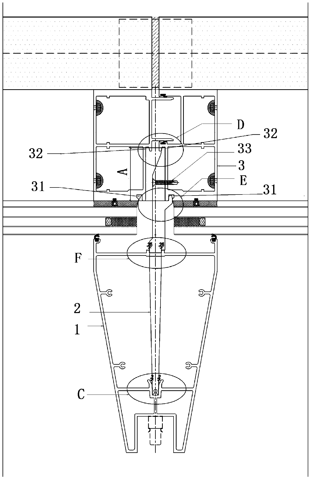
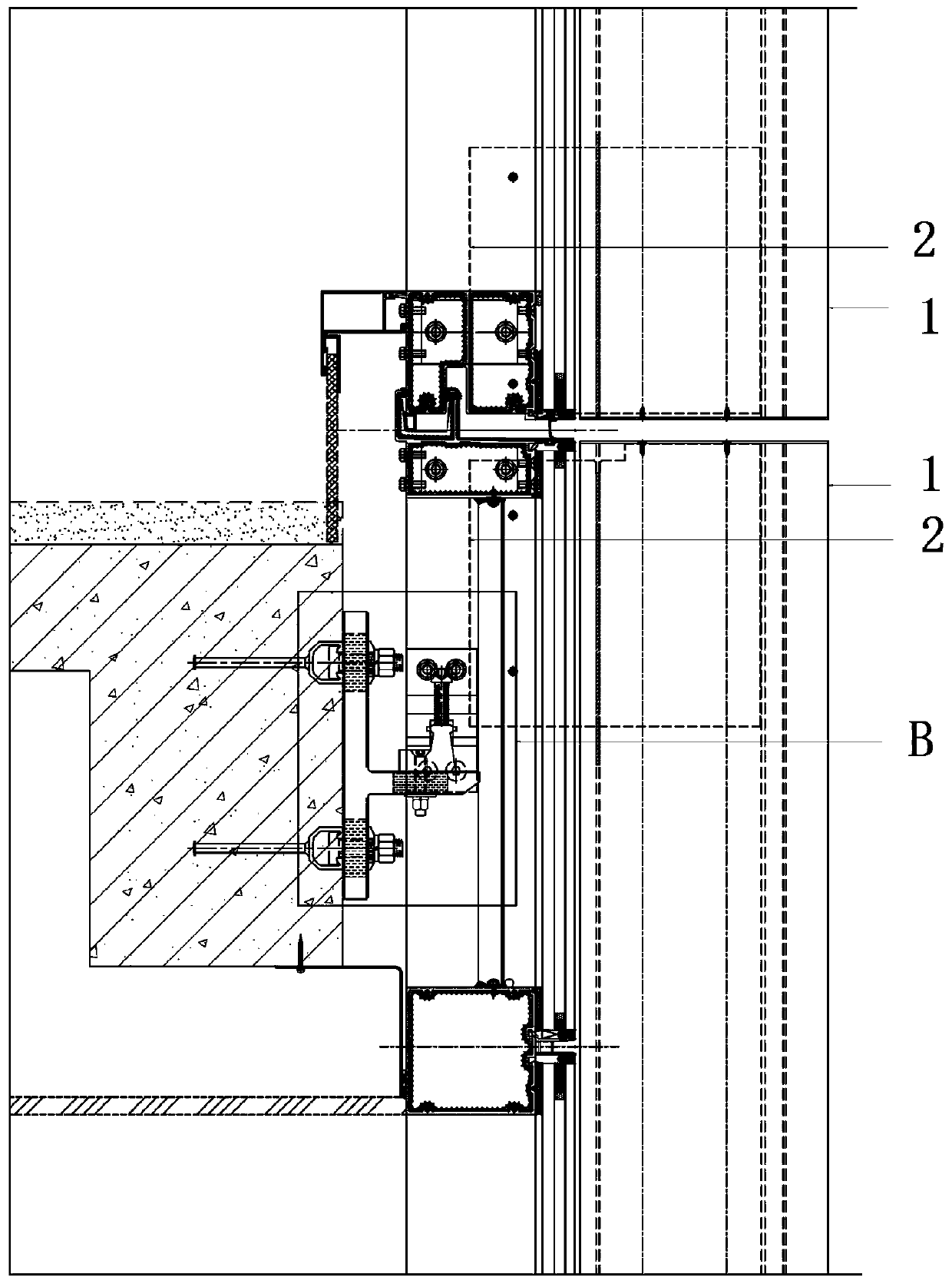
[0025] Such as figure 1 and figure 2 As shown, a decorative strip system with firm connection and simple structure provided by the present invention includes a decorative strip 1, a transfer support arm 2, a column 3 and a sealing plate 4, and the decorative strip 1 is fixed on the On the column 3, the transfer support arm 2 is screwed to the column 3 and fixed.

[0026] Such as figure 1 As shown, two insertion grooves are arranged on the front and back of the column 3, that is, the outside and the inside, the vertical insertion groove 31 on the outside and the vertical insertion groove 32 on the inside, and the two insertion grooves are arranged symmetrically. .

[0027] Such as figure 1 and Figure 4 As shown, a vertical notch 11 is provided on the rear end wall of the decorative strip 1 , and a slot 12 is provided in the decorative strip 1 .

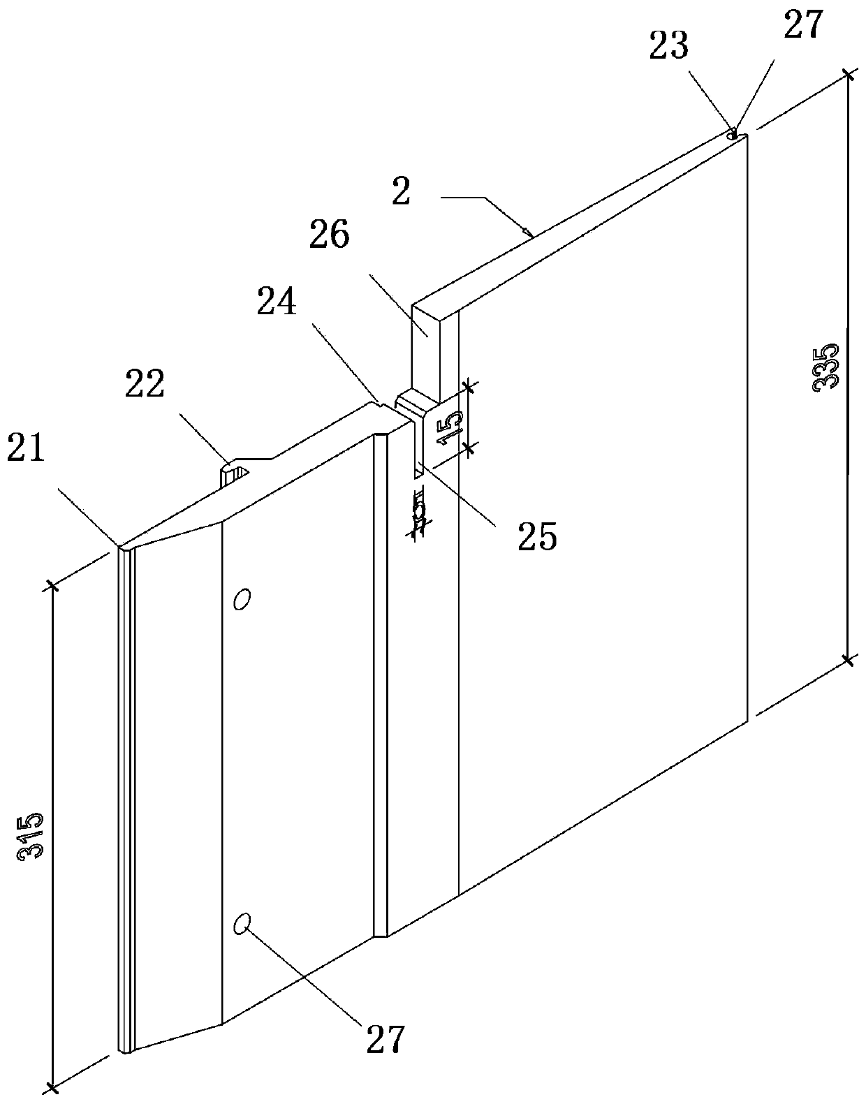
[0028] Such as figure 1 , image 3 and Figure 4 As shown, the transfer support arm 2 is a plate body, the rear part of th...


PUM


Abstract

The invention provides a decorative strip system firm in connection and simple in structure. The system involves a decorative strip (1), adapting supporting arms (2), a stand column (3) and opening sealing plates (4), wherein the decorative strip is fixed to the stand column through the upper adapting supporting arm and the lower adapting supporting arm, and the adapting supporting arms are fixedly connected with the stand column in a threaded mode; two inserting grooves are formed in the stand column in a front-back mode and are symmetrically formed in the left-right direction; the decorativestrip is provided with a vertical notch and an insertion groove; the rear end of each adapting supporting arm is matched with and inserted into the inserting groove in the inner side of the stand column, and inserting head extend from one side of each adapting supporting arm and is matched with and inserted into the other vertical inserting groove in the outer side of the stand column; the frontend of each adapting supporting arm is matched with and inserted into the insertion groove in the decorative strip, and a vertical clamp opening is formed in the end surface of each adapting supporting arm and is matched with and inserted into the vertical notch in the decorative strip; and the opening sealing plates are buckled on the openings of the decorative strip and are fixed to the adaptingsupporting arms. The system enables the decoration strip and the stand column to be firmly connected and is simple in structure.

Description

technical field [0001] The invention relates to the field of building curtain walls, relates to a decorative strip installation structure, and in particular provides a decorative strip system with firm connection and simple structure. Background technique [0002] In the field of architectural curtain walls, the decorative strip system is the most common form of curtain wall. Decorative strips can increase the layering of building facades. Decorative strips with variable shapes make the appearance of buildings more beautiful. Decorative strips with controllable lights can make buildings more shining at night and add color to the city. Most of the decorative strips are cantilever structural systems, and the amount of cantilever depends on the architectural effect. However, in order to achieve the novelty of the building facade or highlight the layered sense of the building facade, the amount of cantilever of the decorative strips is increasing. bigger. In monsoon climate re...

Claims


Application Information

Patent Timeline
Patent Type & Authority Applications(China)
IPC IPC(8): E04B2/88E04F19/02
CPCE04B2/88E04F19/02
Inventor 罗参锦郑胜林梁德阳高阳李娜
Owner JANGHO GRP
Learn More