
Decoupled electromechanical hydraulic integrated brake boosting system

A brake booster, electromechanical technology, applied in the direction of brake, brake transmission, transportation and packaging, can solve problems such as difficulty in providing braking force, pedal force loss, complex structure, etc., and achieve a wide range of applications, large deceleration, The effect of a compact system

Pending Publication Date: 2020-04-28
苏州科美澄汽车科技有限公司
View PDF0 Cites 1 Cited by
  • Summary
  • Abstract
  • Description
  • Claims
  • Application Information

AI Technical Summary

Problems solved by technology

[0004] However, the current electro-hydraulic power-assisted braking system also has some problems. In some systems, the pedal force and power assist are coupled through the reaction disc, which is large in size and complex in structure. It requires complex control algorithms to ensure the pedal feel, and it cannot be decoupled by itself. It is necessary to cooperate with other systems to achieve greater braking energy recovery. In addition, some electro-hydraulic booster systems are decoupled through gaps and pedal simulators. This system completely relies on springs as pedal simulators and needs to limit the spring force, but the pedals It feels that the simulated spring will cause the pedal force to be light and cause pedal force loss, and the pedal does not have the braking hysteresis of the traditional system. At the same time, in the failure mode, the pedal stroke will be greatly increased, and it is difficult to provide sufficient braking force

Method used


Image

  • Decoupled electromechanical hydraulic integrated brake boosting system
  • Decoupled electromechanical hydraulic integrated brake boosting system

Examples


Embodiment Construction

[0022] The following will clearly and completely describe the technical solutions in the embodiments of the present invention. Obviously, the described embodiments are only some of the embodiments of the present invention, rather than all the embodiments. Based on the embodiments of the present invention, all other embodiments obtained by persons of ordinary skill in the art without making creative efforts belong to the protection scope of the present invention.

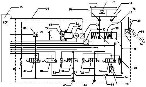
[0023] Such as figure 1 As shown, a decoupled electromechanical-hydraulic integrated brake booster system includes an electronic control unit ECU10, an oil pot 12, and a hydraulic unit 14. The hydraulic unit 14 includes a brake master cylinder 16, a pedal feeling simulator 18, a travel sensor 20, The booster master cylinder 22, the transmission mechanism connected with the piston 24 of the booster master cylinder 22, the inner cavity of the brake master cylinder 16 is divided into a first working chamber 30 and a sec...


PUM


Abstract

The invention relates to a decoupled electromechanical hydraulic integrated brake boosting system. The system comprises an electronic control unit (ECU), an oil can and a hydraulic unit, the hydraulicunit comprises a brake master cylinder, a pedal feeling simulator, a stroke sensor, a boosting master cylinder and a transmission mechanism connected with a piston of the boosting master cylinder, the inner cavity of the brake master cylinder is divided into a first working cavity and a second working cavity by a first piston and a second piston, the first working cavity is connected with a firstnormally closed valve and a first normally open valve, the first normally-closed valve is connected with a pedal feeling simulator, the second working cavity is connected with a second normally-openvalve, the inner cavity of the boosting master cylinder is connected with a second normally-closed valve and a third normally-closed valve, the first normally-open valve and the second normally-closedvalve are both connected with the first output port of the hydraulic unit, and the second normally-open valve and the third normally-closed valve are both connected with the second output port of thehydraulic unit. The brake master cylinder with a small cylinder diameter is adopted, so when the brake master cylinder fails, higher brake pressure can be established through the same pedal force, larger deceleration is achieved, and recovery of all brake energy is achieved.

Description

technical field [0001] The invention relates to a brake booster system, in particular to a decoupled electromechanical-hydraulic integrated brake booster system. Background technique [0002] With the increasing requirements for energy saving and environmental protection, and the continuous development of vehicle electrification and intelligent technology, the traditional vacuum-assisted hydraulic braking system is difficult to meet the requirements of electric vehicles and smart vehicles for the braking system. Electric vehicles cannot provide a vacuum source like traditional internal combustion engine vehicles. The use of vacuum boosters requires additional electronic vacuum pumps. Electronic vacuum pumps will increase energy consumption, cause vacuum noise, and their life is difficult to meet the life requirements of the entire vehicle. At the same time, electric vehicles require braking systems. A certain decoupling capability is used to maximize the recovery of braking ...

Claims


Application Information

Patent Timeline
Patent Type & Authority Applications(China)
IPC IPC(8): B60T13/58B60T13/74B60T8/40B60T13/66
CPCB60T8/409B60T13/58B60T13/662B60T13/745
Inventor 洪英博李守卫
Owner 苏州科美澄汽车科技有限公司
Learn More