Special milling cutter and chuck for CNC milling machine

A CNC milling machine and milling cutter technology, applied in the field of machining, can solve the problems of low efficiency and high inner hole roughness, and achieve the effects of improving machining accuracy, improving work efficiency, and simple and reliable disassembly and combination methods.

Active Publication Date: 2021-08-17
浙江海拓环宇传动科技有限公司
View PDF10 Cites 0 Cited by
  • Summary
  • Abstract
  • Description
  • Claims
  • Application Information

AI Technical Summary

Problems solved by technology

[0003] When CNC machine tools are used to process holes, the workpiece is usually placed on the workbench, and a twist drill is clamped on the chuck of the CNC milling machine, and the inner hole is drilled on the workpiece by the twist drill, but the drilled inner hole is rough. The high degree of precision requires secondary processing. Usually, the workpiece is removed, placed on another CNC milling machine, and a reamer is clamped on the chuck of another CNC milling machine. Hole finishing, not only need to move the workpiece multiple times, but also need to reposition the workpiece after handling, the efficiency is low

Method used


Image

  • Special milling cutter and chuck for CNC milling machine
  • Special milling cutter and chuck for CNC milling machine
  • Special milling cutter and chuck for CNC milling machine

Examples


Embodiment Construction

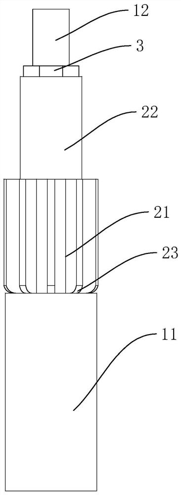
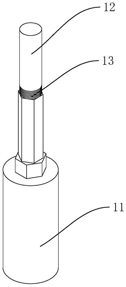
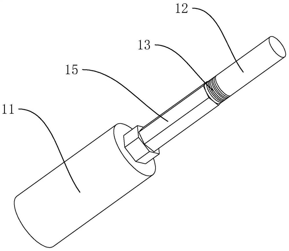
[0024] refer to Figure 1 to Figure 7 The embodiment of a special milling cutter and chuck for a CNC milling machine of the present invention will be further described.

[0025] In the description of the present invention, it should be noted that for orientation words, such as the term "center", "horizontal (X)", "longitudinal (Y)", "vertical (Z)", "length", " Width", "Thickness", "Top", "Bottom", "Front", "Back", "Left", "Right", "Vertical", "Horizontal", "Top", "Bottom", "Inner ", "outside", "clockwise", "counterclockwise" and other indication orientations and positional relationships are based on the orientation or positional relationship shown in the drawings, and are only for the convenience of describing the present invention and simplifying the description, rather than indicating or implying the Means that a device or element must have a specific orientation, be constructed and operated in a specific orientation should not be construed as limiting the specific protecti...


PUM


Abstract

The invention discloses a special milling cutter for a CNC milling machine, which includes a twist drill and a reamer, the twist drill includes a first cutter head and a first handle, and the reamer includes a second cutter head and a second handle. The second knife head and the second knife handle are hollowly arranged to form a mounting hole, the reamer is sleeved on the first knife handle, the end of the second knife head contacts the end of the first knife head, and the end of the first knife handle The part protrudes out of the second tool handle. The invention combines the twist drill and the reamer, and at the same time can drill and finish the hole on the workpiece, without the need to carry the product twice or replace the tool, and without the need for secondary positioning, and the product accuracy is higher. , higher processing efficiency.

Description

technical field [0001] The invention belongs to the field of mechanical processing, and more specifically relates to a special milling cutter and chuck for a numerically controlled milling machine. Background technique [0002] A milling cutter is a rotating tool with one or more teeth for milling. When working, each knife tooth cuts off the allowance of the workpiece intermittently in turn. Milling cutters are mainly used for machining planes, steps, grooves, forming surfaces and cutting off workpieces on milling machines. [0003] When CNC machine tools are used to process holes, the workpiece is usually placed on the workbench, and a twist drill is clamped on the chuck of the CNC milling machine, and the inner hole is drilled on the workpiece by the twist drill, but the drilled inner hole is rough. The high degree of precision requires secondary processing. Usually, the workpiece is removed, placed on another CNC milling machine, and a reamer is clamped on the chuck of ...

Claims


Application Information

Patent Timeline
Patent Type & Authority Patents(China)
IPC IPC(8): B23B51/08B23B51/12B23B31/02
CPCB23B31/02B23B51/08B23B51/12
Inventor 李默
Owner 浙江海拓环宇传动科技有限公司
Why Eureka
Try Eureka