Auxiliary alignment device and method for beams of double-beam light trap

A technology of alignment device and double beam, applied in optics, optical components, testing optical performance, etc., can solve the problems of poor consistency and low precision, and achieve the effect of promoting development, high repeatability, and promoting popularization and application.

Active Publication Date: 2020-04-24
ZHEJIANG UNIV +1
View PDF14 Cites 0 Cited by
  • Summary
  • Abstract
  • Description
  • Claims
  • Application Information

AI Technical Summary

Problems solved by technology

[0010] In view of the technical status of the double-beam optical trap, the adjustment of the optical path of the two beams of the existing dual-beam optical trap relies on human judgment, poor consistency, and low precision. The present invention proposes a dual-beam optical trap beam-assisted alignment The device and method use a specially designed alignment device to detect the position of the centerline of the beam through a four-quadrant position detector (QPD), providing an objective standard for judging the alignment effect of the beam, thereby contributing to the efficient and high-precision improvement of dual Beam path alignment

Method used


Image

  • Auxiliary alignment device and method for beams of double-beam light trap
  • Auxiliary alignment device and method for beams of double-beam light trap
  • Auxiliary alignment device and method for beams of double-beam light trap

Examples


Embodiment Construction

[0042] Below in conjunction with accompanying drawing and embodiment the present invention will be further described:

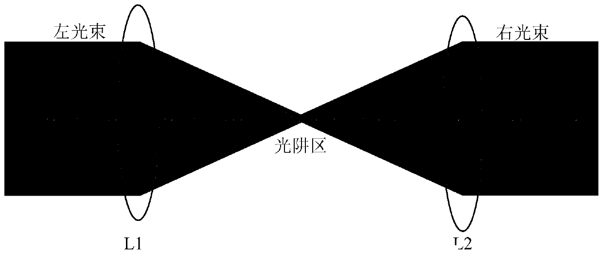
[0043] figure 2 It is a schematic diagram of a double-beam light trap, which mainly includes two lenses L1 and L2 and two beams of parallel light incident on the left and right. The two beams of parallel light generally adopt two vertical polarization states output by the same laser, and the typical laser is a 1064nm laser. The focal points of the two lenses L1 and L2 coincide, and respectively focus the two beams of flat light incident on the left and right on the central focus position, thereby forming a light trap area at the focal point. The center of the light trap is a stable point. Nanospheres have the function of trapping and suspending. After the micro-nano balls are captured, they are supported by the optical force of the light trap, and there is no mechanical support in the environment. By pumping a vacuum, the interference of the micro-nano bal...


PUM


Abstract

The invention discloses an auxiliary alignment device and method for beams of a double-beam light trap. The device is placed at the center of the light trap, and is characterized in that a pair of triangular prisms are right-angled triangles which are arranged in a mode that the planes where the right-angle edges on one sides are located are completely connected in an attached manner and the planes where the right-angle edges on the other sides are located are arranged in parallel to form a parallelogram prism, a plane mirror is horizontal with the reflecting surface facing upward, one of theplanes where the right-angle edges on the other side are located is fixedly arranged on one half side of the plane mirror in an attached manner, and the plane where the bevel edges of the pair of triangular prisms are located is plated with a semi-transparent semi-reflecting film; a pair of four-quadrant position detectors are horizontally arranged on the same plane and located above the plane mirror and the pair of triangular prisms. According to the invention, optical adjustment of the beams of the light trap can be simply and effectively assisted, the performance of the light trap is improved, and an efficient, rapid, convenient and consistent adjustment scheme is provided for a light force suspension system taking the light trap as a core component.

Description

technical field [0001] The invention relates to a light beam alignment device and alignment method of an instrument and a sensing system using an optical suspension system as the basis of measurement, which belong to the technical field of optical precision measurement, and in particular relates to a double-beam optical trap beam-assisted alignment Apparatus and methods. Background technique [0002] The optical trap is the core optical path and key of the optical levitation system. The optical levitation system is an emerging subject based on technologies such as laser control, laser cooling, and laser capture. Through the optical force of the laser beam, the micro Nanoparticles (typically such as micro-nano balls) are suspended, and the particles are supported by light force, replacing the mechanical support structure; thereby isolating the interaction between the particle and the environment, and avoiding various environmental factors, such as vibration, heat conduction, ...

Claims


Application Information

Patent Timeline
Patent Type & Authority Applications(China)
IPC IPC(8): G02B27/62G01M11/02
CPCG01M11/02G02B27/62
Inventor 陈杏藩李楠胡慧珠刘承高晓文
Owner ZHEJIANG UNIV
Why Eureka
Try Eureka