
Self-locking gas valve

A gas and valve technology, applied in valve details, valve devices, valve operation/release devices, etc., can solve problems such as loss of self-locking, poor self-locking effect, and inability to automatically open, etc., to increase safety and reliability, and simple structure , It is beneficial to the effect of troubleshooting

Active Publication Date: 2020-04-24
宁波志清智控科技有限公司
View PDF7 Cites 3 Cited by
  • Summary
  • Abstract
  • Description
  • Claims
  • Application Information

AI Technical Summary

Problems solved by technology

[0002] Valves are devices used to control flow on pipelines. There are many types. In recent years, in order to increase the safety of valves, new valves such as self-locking valves and automatic detection valves have appeared. However, traditional self-locking valves often use a single self-locking valve. The self-locking device is locked, and the self-locking effect is poor. The valve after self-locking can be opened at will, which loses the meaning of self-locking. Although the automatic detection valve can automatically close when a gas leak occurs, the detection device detects that the gas concentration When the gas concentration decreases, it will automatically open the valve, but the decrease of the gas concentration does not mean that the fault has been completely eliminated. At this time, opening the valve is still dangerous. The most reliable method is to manually open the valve after the fault is eliminated. The valve with lock and detection function will automatically close after detecting a fault, and then it cannot be opened automatically, and the opening of its self-locking device requires a key to ensure that the valve will not be opened at will after it is closed

Method used


Image

  • Self-locking gas valve
  • Self-locking gas valve
  • Self-locking gas valve

Examples


Embodiment Construction

[0016] Combine below Figure 1-4 The present invention is described in detail, and for convenience of description, the orientations mentioned below are now stipulated as follows: figure 1 The up, down, left, right, front and back directions of the projection relationship itself are the same.

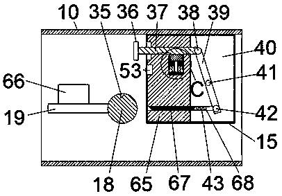
[0017] refer to Figure 1-4 , a self-locking gas valve according to an embodiment of the present invention, including a valve body 10, a pipe wall 12 penetrating left and right is fixed inside the valve body 10, and a right side extending to the right is fixed inside the pipe wall 12. The air passage 13 and the left air passage 26 extending to the left, the inside of the pipe wall 12 is fixed with a ball valve 25 located in the middle of the right air passage 13 and the left air passage 26, and the inside of the ball valve 25 is fixed with a communication The air passage 14, the upper top wall and the lower bottom wall of the right air passage 13 and the communication air passage 14 ar...


PUM


Abstract

The invention discloses a self-locking gas valve. The gas valve comprises a valve body, a pipe wall which is through left and right is fixedly arranged in the valve body, a right air duct extending rightwards and a left air duct extending leftwards are fixedly arranged in the pipe wall, a ball valve located in the middle of the right air duct and the left air duct is fixedly arranged in the pipe wall, an upper cavity located in the upper side end face of the pipe wall is formed in the valve body, a lower cavity located in the lower side end face of the pipe wall is formed in the valve body, amanual control device is arranged in the upper cavity, and an electric control device is arranged in the lower cavity. The gas valve is simple in structure and convenient to use, and manual and electric control of the valve is achieved. Meanwhile, the valve is provided with a self-locking device, so that the valve cannot be opened easily after being closed, and the safety and reliability of the valve are improved. Meanwhile, the valve can detect the gas concentration in the air and can be automatically closed, troubleshooting is facilitated, and the valve plays an important role in safe production of the gas industry.

Description

technical field [0001] The invention relates to the technical field of valves, in particular to a self-locking gas valve. Background technique [0002] Valves are devices used to control flow on pipelines. There are many types. In recent years, in order to increase the safety of valves, new valves such as self-locking valves and automatic detection valves have appeared. However, traditional self-locking valves often use a single self-locking valve. The self-locking device is locked, and the self-locking effect is poor. The valve after self-locking can be opened at will, which loses the meaning of self-locking. Although the automatic detection valve can automatically close when a gas leak occurs, the detection device detects that the gas concentration When the gas concentration decreases, it will automatically open the valve, but the decrease of the gas concentration does not mean that the fault has been completely eliminated. At this time, opening the valve is still dangerou...

Claims


Application Information

Patent Timeline
Patent Type & Authority Applications(China)
IPC IPC(8): F16K5/06F16K31/05F16K37/00F16K35/16
CPCF16K5/0647F16K31/055F16K35/16F16K37/005
Inventor 不公告发明人
Owner 宁波志清智控科技有限公司
Learn More