Electronic remote control lock well lid for prison
An electronic remote control and manhole cover technology, which is used in building locks, non-mechanical transmission-operated locks, water conservancy projects, etc., can solve the problems of wear and tear of lock and key parts, affecting the service life of unlocking operability locks, and difficulty in unlocking, so as to prolong the service life. , Easy to manage, prevent moisture absorption and corrosion damage
- Summary
- Abstract
- Description
- Claims
- Application Information
AI Technical Summary
Problems solved by technology
Method used
Image
Examples
Embodiment 1
[0043] The lock of prison manhole cover is a kind of mechanical lock. Due to the serious wear and tear of the lock and key parts for many years, it is difficult to unlock, and the lock or key needs to be replaced, which seriously affects the operability of unlocking and the service life of the lock.
[0044] In view of the above problems, the present invention provides an electronic remote-controlled manhole cover for prisons.
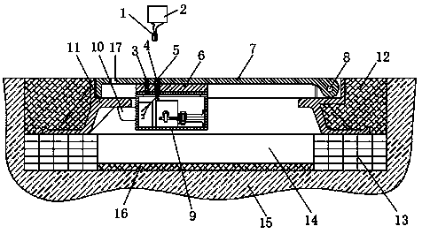
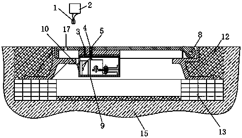
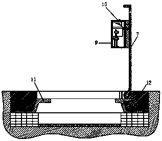
[0045] For details, please refer to Figure 4-6 , an electronic remote lock well cover for prisons, including a cover body 7, the cover body 7 is fixed on the well base 11 by rotation of the well cover rotating shaft 8, and the well cover also includes a lock body 9 slidingly installed with a deadbolt 10, so The lock body 9 is installed on the surface of the lower end of the cover body 7 away from the shaft 8 of the well cover;
[0046] Among them, such as Figure 4 and Figure 5 , the inside of the lock body 9 cooperates with the deadbolt 10 to ope...
Embodiment 2
[0054] The embodiment of the present invention is further limited on the basis of embodiment 1.
[0055] like Figure 4-6 , the magnetic push-pull structure is provided with a link 109, and one end of the link 109 is connected to the dead bolt 10 through the push-pull hook 105 on the tongue lock, and the other end is connected to the electromagnetic push-pull rod 108 through the electromagnetic push-pull hook 114, and the electromagnetic push-pull hook 114 and the electromagnetic push-pull rod 108 are connected by a core iron 111, and the electromagnetic push-pull rod 108 is electrically connected to the control switch 116 through the electric wire 115, and the control switch 116 is installed on the inner wall of the control room 125; and the connecting rod 109 is L-shaped , the L-shaped corner of the link 109 is provided with a support plate 113, one end of the support plate 113 is fixed on the inner wall of the control room 125, and the other end is rotated and fixed by the ...
Embodiment 3
[0068] The embodiment of the present invention is further limited on the basis of embodiment 1 and embodiment 2.
[0069] see Figure 1-3 Concrete 12 is arranged around the well block 11, and bricks 13 are installed at the bottom of the concrete 12, and the inner side of the bricks 13 is a brick well 14, and a concrete well bottom 16 is laid at the bottom of the brick well 14, and the concrete well bottom A foundation 15 is provided outside the bottom of 16 .
[0070] The working principle of the present invention is: the prison of the present invention uses electronic remote control to lock the manhole cover, and the external remote control switch closes the circuit of the electromagnetic push-pull rod 108 after receiving the electromagnetic signal through the antenna 3, and the coil of the electromagnetic push-pull rod 108 generates electromagnetic force, which attracts the core iron 111, The electromagnetic push-pull hook 114 of the electromagnetic push-pull rod 108 pulls ...
PUM
 Abstract
Description
Claims
Application Information
 - Generate Ideas
- Intellectual Property
- Life Sciences
- Materials
- Tech Scout
- Unparalleled Data Quality
- Higher Quality Content
- 60% Fewer Hallucinations
Browse by: Latest US Patents, China's latest patents, Technical Efficacy Thesaurus, Application Domain, Technology Topic, Popular Technical Reports.
© 2025 PatSnap. All rights reserved.Legal|Privacy policy|Modern Slavery Act Transparency Statement|Sitemap|About US| Contact US: help@patsnap.com


