Gantry crane for mounting equipment

A technology for installing equipment and gantry cranes, which is applied in the field of gantry cranes and can solve the problems of high cost, limited use area and large floor space.

Pending Publication Date: 2020-04-24
SHANDONG HONGWANG INDUSTRY CO LTD
View PDF0 Cites 1 Cited by
  • Summary
  • Abstract
  • Description
  • Claims
  • Application Information

AI Technical Summary

Problems solved by technology

[0002] In stainless steel processing workshops, there are a large number of heavy parts or equipment that need to be moved, debugged and installed every day. These parts or equipment have exceeded the weight that a single person can carry, and often require multiple workers to work together. However, there is no way to do it manually for large and overweight heavy objects.
With the acceleration of urbanization, all walks of life are gradually realizing semi-automatic mechanization and full-automatic mechanization to reduce labor intensity and improve production efficiency. Many enterprises have begun to introduce lifting devices to achieve mechanical lifting. At present, the commonly used mechanical lifting is Cranes using various driving principles have the advantages of reliable lifting and large bearing capacity. However, most of these cranes can only fixedly lift heavy objects in one position. At the same time, they occupy a large area and are expensive. They are mostly used for lifting large outdoor equipment. Due to the limitation of limited use area and high cost, this kind of crane is not very common in the indoor workshops of some small and medium-sized enterprises. Therefore, it is necessary to design a lifting device that is suitable for indoors and can lift heavy objects in different positions. , to facilitate the moving, commissioning and installation of equipment

Method used


Image

  • Gantry crane for mounting equipment
  • Gantry crane for mounting equipment
  • Gantry crane for mounting equipment

Examples


Embodiment Construction

[0019] The technical solutions in the embodiments of the present invention are clearly and completely described below in conjunction with the drawings in the embodiments of the present invention. It should be understood that the specific embodiments described here are only used to explain the present invention, and are not intended to limit the protection scope of the present invention.

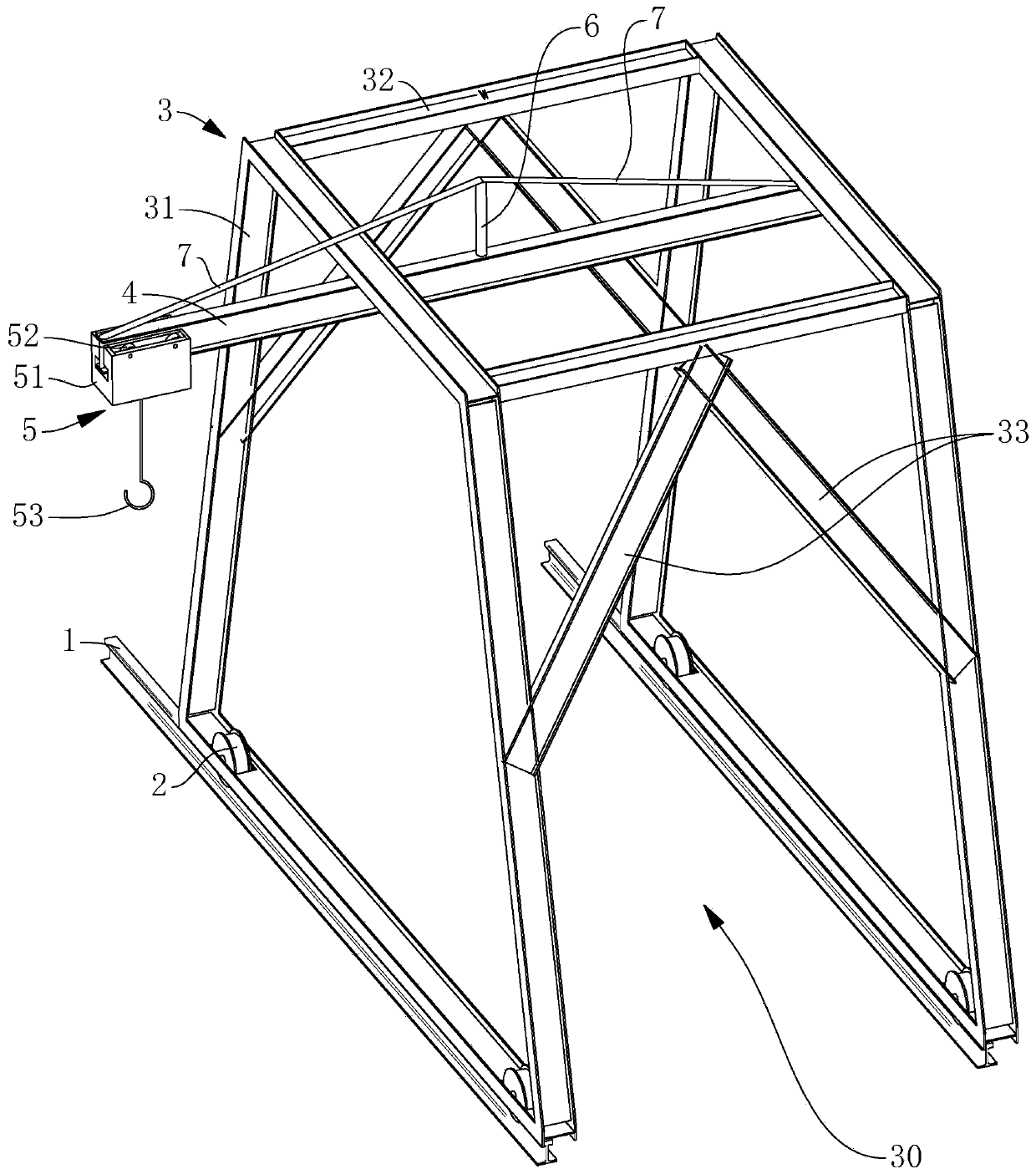
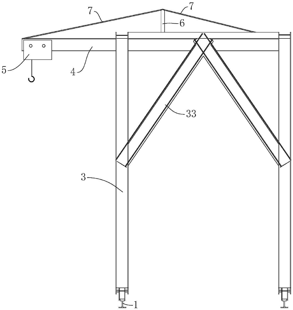
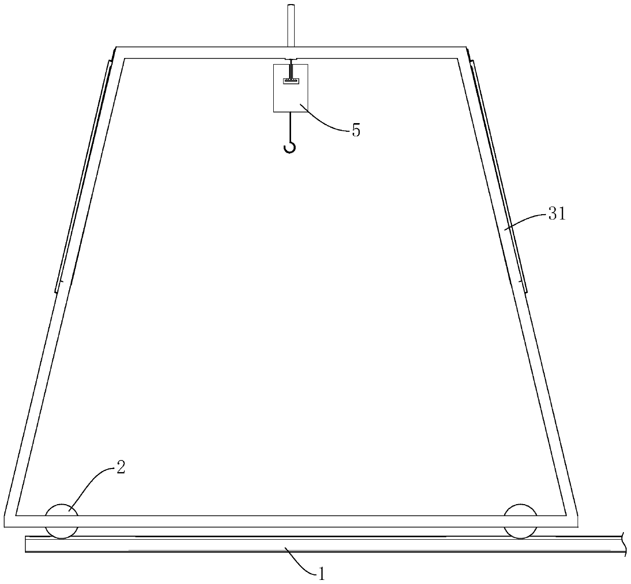
[0020] see Figure 1 to Figure 3 , the present invention provides a gantry crane for installing equipment, comprising a slide rail 1, a pulley 2, a support frame 3, a beam 4 and an electric hoist 5, two slide rails 1 are arranged in parallel, and four bottoms of the support frame 3 are installed Pulley 2, one end of crossbeam 4 is fixed on support frame 3, the other end of crossbeam 4 stretches out the predetermined length of support frame 3, and electric hoist 5 can be arranged on crossbeam 4 slidably along the length direction of crossbeam 4, and support frame 3 is formed with Together wit...


PUM


Abstract

The invention provides a gantry crane for mounting equipment. The gantry crane comprises two parallel slide rails, sliding wheels, a support frame, a cross beam and an electric hoist, wherein the foursliding wheels are mounted at the bottom of the support frame, the electric hoist is slidably arranged on the cross beam in the length direction of the cross beam, one end of the cross beam is fixedon the support frame, the other end of the cross beam extends out of the support frame by a preset length, a hoisting space is formed in the support frame, and the electric hoist can slide a hoisted heavy object in a reciprocating mode within the range from the extending end of the cross beam to the hoisting space. The gantry crane for mounting the equipment can be used for movably hoisting heavyobjects at different positions, is small in occupied area and low in cost, can be universally used for hoisting indoor heavy objects, and equipment moving, debugging and mounting is facilitated.

Description

technical field [0001] The invention relates to a lifting device, in particular to a gantry crane used for installing equipment. Background technique [0002] In stainless steel processing workshops, there are a large number of heavy parts or equipment that need to be moved, debugged and installed every day. These parts or equipment have exceeded the weight that a single person can carry, and often require multiple workers to work together. And there is no way to do it manually for the large and overweight heavy objects. With the acceleration of urbanization, all walks of life are gradually realizing semi-automatic mechanization and full-automatic mechanization to reduce labor intensity and improve production efficiency. Many enterprises have begun to introduce lifting devices to achieve mechanical lifting. At present, the commonly used mechanical lifting is Cranes using various driving principles have the advantages of reliable lifting and large bearing capacity. However, ...

Claims


Application Information

Patent Timeline
Patent Type & Authority Applications(China)
IPC IPC(8): B66C5/04B66C11/06
CPCB66C5/04B66C11/06
Inventor 卢威戴泽辉
Owner SHANDONG HONGWANG INDUSTRY CO LTD
Why Eureka
Try Eureka