Part stamping method

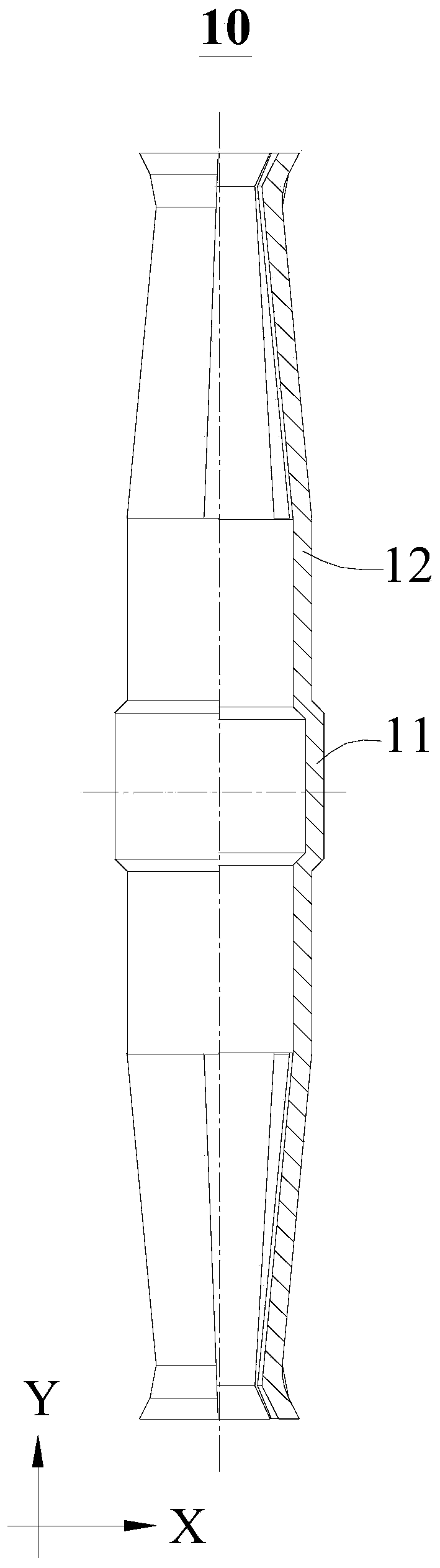
A technology of parts and protrusions, which is applied to other household appliances, household appliances, applications, etc., can solve problems such as difficulty in enclosing the extension 12, breakage, large deformation, etc., and achieve the effect of improving consistency

Active Publication Date: 2020-04-24
深圳市君灏精密工业有限公司
View PDF7 Cites 0 Cited by
  • Summary
  • Abstract
  • Description
  • Claims
  • Application Information

AI Technical Summary

Problems solved by technology

However, because there is a sudden change in diameter between the raised portion 11 and the extended portion 12 in the part 10, rather than a gradual change, when stamping the part (drawn region 211) corresponding to the raised portion 11 in the planar structure figure, it is inevitable The structural region (extension region 22) corresponding to the extension part 12 is pulled and deformed. At this time, the extension region 22, especially the region close to the deep-drawing region 211, is greatly deformed, and its long and short sides change, making it difficult to meet the design requirements. In addition, since the extension area 22 is also subjected to the clamping force of the clamp, under the action of the internal stress and clamping force of inward bending, this area is prone to deformation or even fracture

Method used


Image

  • Part stamping method
  • Part stamping method
  • Part stamping method

Examples


Embodiment Construction

[0029] In order to make the object, technical solution and advantages of the present invention clearer, the present invention will be further described in detail below in conjunction with the accompanying drawings and embodiments. It should be understood that the specific embodiments described here are only used to explain the present invention, not to limit the present invention.

[0030] It should be noted that when an element is referred to as being “fixed” or “disposed on” another element, it may be directly on the other element or be indirectly on the other element. When an element is referred to as being "connected to" another element, it can be directly connected to the other element or indirectly connected to the other element.

[0031] In addition, the terms "first" and "second" are used for descriptive purposes only, and cannot be interpreted as indicating or implying relative importance or implicitly specifying the quantity of indicated technical features. Thus, a ...


PUM


Abstract

The invention is suitable for the field of structure machining, and provides a part stamping method. The method is used for punching redundant materials on a sheet and punching a cylindrical part. Thepart comprises a protruding part located in the middle and two extending parts which are connected with the protruding part respectively and are symmetrically arranged front and back. The diameter ofthe protruding part is larger than that of the extending parts. The part stamping method comprises the steps of preparing a sheet, specifically, the sheet comprises a deep drawing area used for forming the protruding part, an extending area used for forming the extending parts, a material belt connected with the extending area and a cutting area arranged among the material belt, the extending area and the deep drawing area in a filling mode; stamping a boss: stamping in the deep drawing area to form a boss protruding downwards; punching and blanking: punching the cutting area; and stamping and rounding: stamping and rounding the boss and the extending area as a whole. By adopting the part stamping method provided by the invention, the part production quality can be improved.

Description

technical field [0001] The invention belongs to the field of structure processing, and in particular relates to a part stamping method. Background technique [0002] For cylindrical parts with sudden diameter changes, such as figure 1 In the part shown, the middle part of the part protrudes outwards to form a convex ring, and the diameter of the joint between the convex ring and the upper or lower end decreases sharply. When the part is processed by stamping, the following problems exist: [0003] Due to the complex structure of the parts, most domestic stamping is completed by single-process step-by-step mold stamping, that is, the sheet is clamped and stamped on multiple stamping stations in sequence. Therefore, the number of molds and stamping equipment that needs to be invested is large. Stamping a part requires many people to put into production, the production efficiency is low, and it is difficult to ensure the consistency of product quality. [0004] Some other man...

Claims


Application Information

Patent Timeline
Patent Type & Authority Applications(China)
IPC IPC(8): B21D35/00B21D51/10
CPCB21D35/002B21D51/10
Inventor 冯鹏君刘辉
Owner 深圳市君灏精密工业有限公司
Why Eureka
Try Eureka