
Display panel and manufacturing method

A display panel and equipment technology, applied in semiconductor/solid-state device manufacturing, semiconductor devices, electrical components, etc., can solve the problems of low service life of display panels, cracking of light-emitting layer molecules, high driving voltage, etc.

Active Publication Date: 2020-04-21
KUNSHAN GO VISIONOX OPTO ELECTRONICS CO LTD
View PDF10 Cites 0 Cited by
  • Summary
  • Abstract
  • Description
  • Claims
  • Application Information

AI Technical Summary

Problems solved by technology

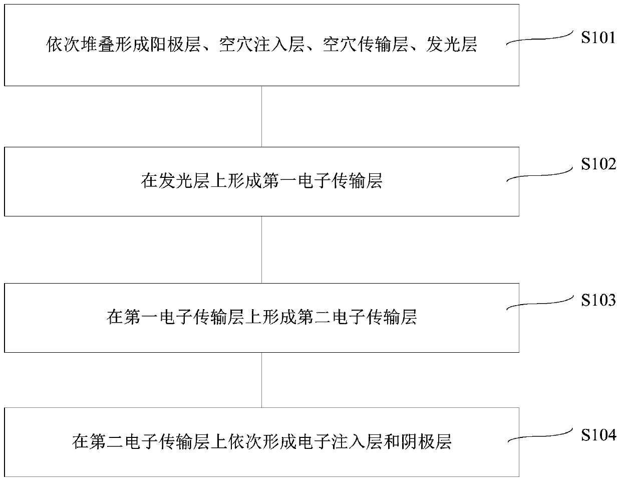
[0005] The embodiment of the present invention provides a display panel and a preparation method to solve the problem that the high driving voltage in the display panel in the prior art causes the organic molecules in the light-emitting layer to crack, The problem of low lifespan of the display panel

Method used


Image

  • Display panel and manufacturing method
  • Display panel and manufacturing method
  • Display panel and manufacturing method

Examples


Embodiment Construction

[0054] In order to make the objectives, technical solutions, and advantages of the embodiments of the present invention clearer, the technical solutions in the embodiments of the present invention will be described clearly and completely in conjunction with the accompanying drawings in the embodiments of the present invention. Obviously, the described embodiments It is a part of the embodiments of the present invention, not all the embodiments. Based on the embodiments of the present invention, all other embodiments obtained by those of ordinary skill in the art without creative work shall fall within the protection scope of the present invention. Therefore, the following detailed description of the embodiments of the present invention provided in the accompanying drawings is not intended to limit the scope of the claimed invention, but merely represents selected embodiments of the present invention.

[0055] In the case of no conflict, the embodiments of the present invention an...


PUM


Abstract

The invention provides a display panel and a manufacturing method. The display panel comprises an anode layer, a hole injection layer, a hole transport layer, a light emitting layer, a first electrontransport layer, a second electron transport layer, an electron injection layer and a cathode layer which are stacked in sequence, wherein a content of a Liq material in the first electron transport layer is greater than the content of an ETM material, and the content of the Liq material in the second electron transport layer is less than the content of the ETM material. In an operation process ofthe display panel, through arrangement of the first electron transport layer and the second electron transport layer, a difference value between an electron transmission rate and a hole transmissionrate is reduced so that composite balance of holes and electrons in a light-emitting layer can be improved, a driving voltage of the display panel is reduced, and a service life of the display panel is prolonged.

Description

Technical field [0001] The invention relates to the field of display technology, in particular to a display panel and a manufacturing method. Background technique [0002] The display panel usually includes a cathode, an electron injection layer, an electron transport layer, a light-emitting layer, a hole transport layer, a hole injection layer, and an anode. The cathode is used to generate electrons, and the anode is used to generate holes. The electrons and holes are in the light-emitting layer. Combining to form excitons, the organic molecules in the light-emitting layer are excited by the excitons, thereby generating a light source. [0003] Since the hole transport rate of the hole transport layer is greater than the electron transport rate of the electron transport layer, the number of holes transported to the light-emitting layer is greater than the number of electrons. These excess holes accumulate in the light-emitting layer, resulting in organic Molecule cleavage increas...

Claims


Application Information

Patent Timeline
Patent Type & Authority Applications(China)
IPC IPC(8): H01L51/50H01L51/56
CPCH10K71/164H10K50/166H10K71/00
Inventor 艾经伟朱修剑
Owner KUNSHAN GO VISIONOX OPTO ELECTRONICS CO LTD
Learn More