
Insulated gate bipolar transistor packaging module

A bipolar transistor and packaging module technology, which is applied in the direction of electric solid-state devices, semiconductor devices, semiconductor/solid-state device components, etc., can solve the problems of low-quality components and circuit layout, cross-wiring, time-consuming and labor-intensive problems, etc.

Active Publication Date: 2020-04-21
广东芯聚能半导体有限公司
View PDF6 Cites 0 Cited by
  • Summary
  • Abstract
  • Description
  • Claims
  • Application Information

AI Technical Summary

Problems solved by technology

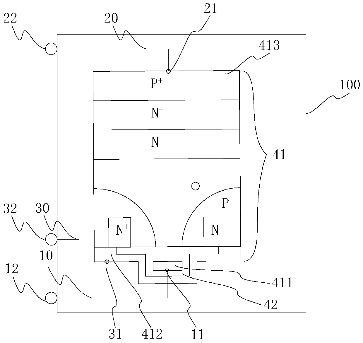
[0004] However, the order of the pins of the existing IGBT package modules is generally the gate (G), the collector (C) and the emitter (E), such as figure 1 As shown in , the gate (G) is used to input the driving voltage of the IGBT, and during the design and layout of the integrated circuit board, it is likely that the high-power driving circuit components are densely designed at the bottom of the circuit board, and according to In the pin order of the current IGBT chip, the gate (G) of the drive signal input terminal is at the top, which causes the circuit wiring to cross. The components and circuit layout of the circuit board are of low quality

Method used


Image

  • Insulated gate bipolar transistor packaging module
  • Insulated gate bipolar transistor packaging module
  • Insulated gate bipolar transistor packaging module

Examples


Embodiment Construction

[0031] In order to facilitate the understanding of the present application, the present application will be described more fully below with reference to the relevant drawings. Preferred embodiments of the application are shown in the accompanying drawings. However, the present application can be embodied in many different forms and is not limited to the embodiments described herein. On the contrary, the purpose of providing these embodiments is to make the understanding of the disclosure of the application more thorough and comprehensive.

[0032] Unless otherwise defined, all technical and scientific terms used herein have the same meaning as commonly understood by one of ordinary skill in the technical field to which this application belongs. The terms used herein in the specification of the application are only for the purpose of describing specific embodiments, and are not intended to limit the application. As used herein, the term "and / or" includes any and all combinati...


PUM


Abstract

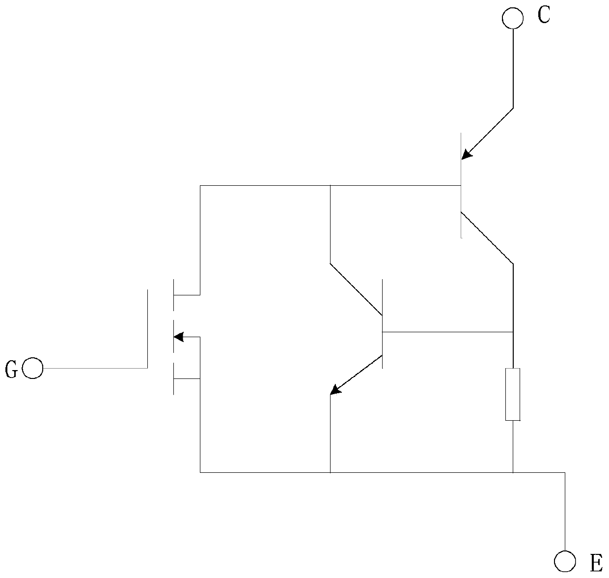
The invention relates to an insulated gate bipolar transistor packaging module. The module comprises an insulated gate bipolar transistor, a collector lead, an emitter lead and a gate lead. A collector leading-out terminal, an emitter leading-out terminal and a gate leading-out terminal are located on the same side of the insulated gate bipolar transistor packaging module, and the emitter leading-out terminal is located between the collector leading-out terminal and the gate leading-out terminal. The emitter leading-out terminal is arranged between the collector leading-out terminal and the gate leading-out terminal so that the collector leading-out terminal and the gate leading-out terminal are positioned on an upper side and a lower side of the emitter leading-out terminal; a driving signal can be conveniently input into an insulated gate bipolar transistor through the collector leading-out terminal and the gate leading-out terminal; an element distribution design and a wiring designcan be conveniently performed on a circuit adopting the insulated gate bipolar transistor packaging module, and meanwhile a circuit application range of the insulated gate bipolar transistor packaging module is expanded.

Description

technical field [0001] The application belongs to the technical field of semiconductor power devices, and in particular relates to an insulated gate bipolar transistor packaging module. Background technique [0002] Insulated Gate Bipolar Transistor (IGBT) is composed of Bipolar Junction Transistor (BJT) and Metal-Oxide-Semiconductor Field-Effect Transistor (MOSFET) The composite fully controlled-voltage-driven-power semiconductor device, which has the characteristics of self-shutdown. Simply put, it is a non-on or off switch. IGBT has no function of amplifying voltage. It can be regarded as a wire when it is turned on, and it is regarded as an open circuit when it is turned off. IGBT combines the advantages of BJT and MOSFET, such as low driving power and saturation voltage drop. [0003] IGBT is the core device of energy conversion and transmission, and the "CPU" of power electronic devices. The use of IGBT for power conversion can improve the efficiency and quality of ...

Claims


Application Information

Patent Timeline
IPC IPC(8): H01L23/043H01L23/10H01L23/48H01L29/739
CPCH01L23/043H01L23/10H01L23/48H01L29/7393
Inventor 池继富周晓阳王亚哲
Owner 广东芯聚能半导体有限公司
Learn More