A room temperature terahertz focal plane array bias voltage adjustment circuit and its application method

A terahertz coke, planar array technology, applied in the field of room temperature terahertz detection, can solve the problems of low precision and difficult debugging, and achieve the effect of strong flexibility

Active Publication Date: 2021-11-09
UNIV OF ELECTRONICS SCI & TECH OF CHINA
View PDF7 Cites 0 Cited by
  • Summary
  • Abstract
  • Description
  • Claims
  • Application Information

AI Technical Summary

Problems solved by technology

The principle of reference source + resistor divider is to change the bias value by changing the resistor ratio. In this way, the voltage resolution is completely determined by the resistor ratio, and it is difficult to debug and the accuracy is not high.

Method used


Image

  • A room temperature terahertz focal plane array bias voltage adjustment circuit and its application method
  • A room temperature terahertz focal plane array bias voltage adjustment circuit and its application method
  • A room temperature terahertz focal plane array bias voltage adjustment circuit and its application method

Examples


Embodiment 1

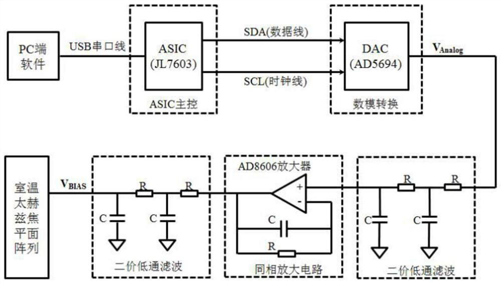
[0037] Taking the ASIC chip JL7603B, the 14-bit D / A converter AD5694 and the 320*240 room temperature terahertz focal plane array detector as examples, a room temperature terahertz focal plane array bias voltage adjustment circuit is described in detail.

[0038] Such as image 3 As shown, the bias voltage adjustment circuit includes sequentially connected PC terminal, ASIC chip, D / A converter, first second-order low-pass filter, non-inverting amplifier circuit, second second-order low-pass filter and room temperature terahertz Focal plane array; the PC end is connected to the ASIC chip through a USB serial port, and the ASIC chip communicates with the PC end by converting the UART to a USB serial port. The SDA pin and the SCL pin of the ASIC chip are connected to the input end of the D / A converter through the SDA data line and the SCL data line. The ASIC chip processes the bias voltage value input from the PC terminal into a corresponding binary value through internal code, ...

Embodiment 2

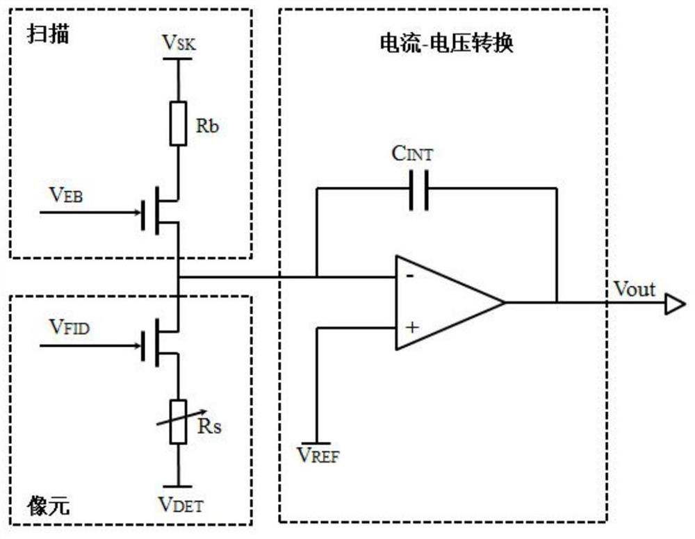
[0059] Such as figure 1 As shown, the room temperature terahertz focal plane array includes a pixel integration circuit based on a terahertz microbolometer, and there are four bias voltages VSK, VEB, VFID and VREF, and the range is between 0-5V. VSK provides the bias voltage for the blind resistor, VEB and VFID respectively control the current of the blind resistor and the equivalent resistance of the terahertz microbolometer, VREF is the reference voltage of the integrator, and the four bias voltages are crucial to the output voltage Vout Different bias voltage drivers will get different output voltage values, so the bias voltage needs to be designed to be adjustable.

[0060] Such as Figure 4 As shown, a method for using a room temperature terahertz focal plane array bias voltage adjustment circuit is provided, including the following steps:

[0061] S1. Input a bias voltage command in the PC-side software, and calculate the decimal value corresponding to the bias voltage...


PUM


Abstract

The invention discloses a room temperature terahertz focal plane array bias voltage adjustment circuit and its application method. An amplification circuit, a second second-order low-pass filter circuit, and a room-temperature terahertz focal plane array, and the PC end is connected to the ASIC chip through a USB serial port line. Input the bias voltage command in the PC-side software, under the control of the ASIC chip, calculate the decimal value of the corresponding bias voltage command into the corresponding binary value, and convert the input binary digital signal into a bias voltage command through the D / A converter Analog signal, the bias command analog signal is output to the first second-order low-pass filter circuit for filtering, then enters the non-inverting operational amplifier for amplification processing, and then is filtered and noise-reduced by the second second-order low-pass filter, and then input to the room temperature terahertz coke planar array. The scheme provides an adjustable bias voltage design method, and the bias voltage design circuit has high precision and low noise.

Description

technical field [0001] The invention relates to the technical field of room temperature terahertz detection, in particular to a room temperature terahertz focal plane array bias voltage adjustment circuit and a design method thereof. Background technique [0002] Terahertz radiation refers to electromagnetic waves with a frequency in the range of 0.1-10THz. Compared with other electromagnetic wave frequency bands, it has the characteristics of broadband, low energy, transient, water fear, and penetration. It is used in wireless communication, homeland security, and nondestructive detection. , biomedicine and other aspects have a wide range of applications. [0003] Terahertz detection and imaging technology is the focus of terahertz science and technology research and the key technology for the wide application of terahertz science and technology. At present, more and more room temperature terahertz real-time imagers integrating two-dimensional sensors are being developed a...

Claims


Application Information

Patent Timeline
Patent Type & Authority Patents(China)
IPC IPC(8): G01J5/24
CPCG01J5/24G01J2005/0077G01J2005/202
Inventor 王军张云逵张江威谢哲远苟君
Owner UNIV OF ELECTRONICS SCI & TECH OF CHINA
Why Eureka
Try Eureka