
A fluorescent ceramic and its preparation method, light source device and projection device

A fluorescent ceramic and fluorescent technology, applied in projection devices, chemical instruments and methods, optics, etc., can solve the problems of low blue light absorption rate, insufficient bonding strength, weak luminous performance, etc., and achieve high luminous intensity and improved structural strength Effect

Active Publication Date: 2021-10-26
APPOTRONICS CORP LTD
View PDF13 Cites 0 Cited by
  • Summary
  • Abstract
  • Description
  • Claims
  • Application Information

AI Technical Summary

Problems solved by technology

Traditional YAG:Ce pure-phase fluorescent ceramics are weaker than silica gel and glass-encapsulated wavelength conversion devices in terms of luminous performance, especially when fluorescent ceramics are ultra-thin packaged, the loss of light efficiency due to low blue light absorption rate and total reflection at the interface is very large
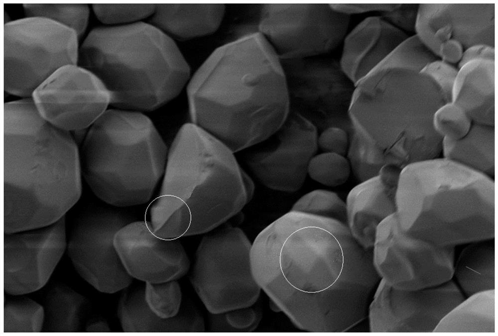
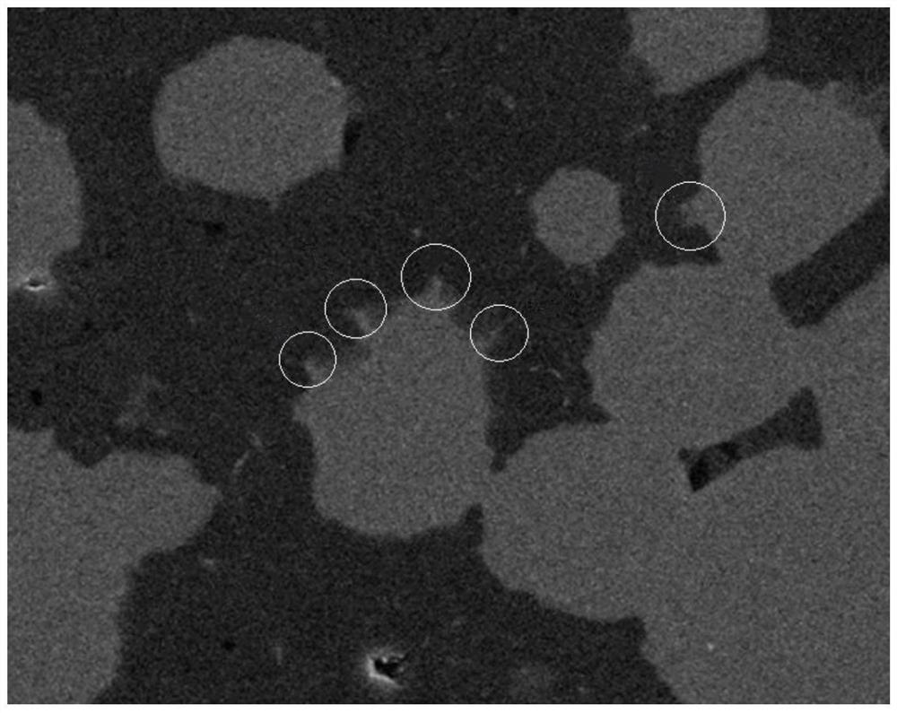
At present, in order to improve the luminous performance of fluorescent ceramics, phosphor particles with larger sizes are preferred, because most of the existing phosphor particles are irregular in shape, such as figure 1 As shown by , there are many raised sharp corners on the surface (such as figure 1 Shown in the part circled by the circle), this kind of irregular surface will easily enter the liquid phase and material migration during the sintering process of preparing fluorescent ceramics (such as figure 2 As shown in the part circled by the circle), the surface integrity of the phosphor particles is destroyed, thereby affecting the luminescent performance of the phosphor particles; in addition, the phosphor particles that generate liquid phase and material migration will also affect the nearby Al 2 o 3 The growth of crystal grains leads to insufficient bonding strength here, which seriously affects the reliability of fluorescent ceramics
[0004] Therefore, there is an urgent need for a new type of fluorescent ceramics to improve the low luminous efficiency of current fluorescent ceramics.

Method used


Image

  • A fluorescent ceramic and its preparation method, light source device and projection device
  • A fluorescent ceramic and its preparation method, light source device and projection device
  • A fluorescent ceramic and its preparation method, light source device and projection device

Examples


preparation example Construction

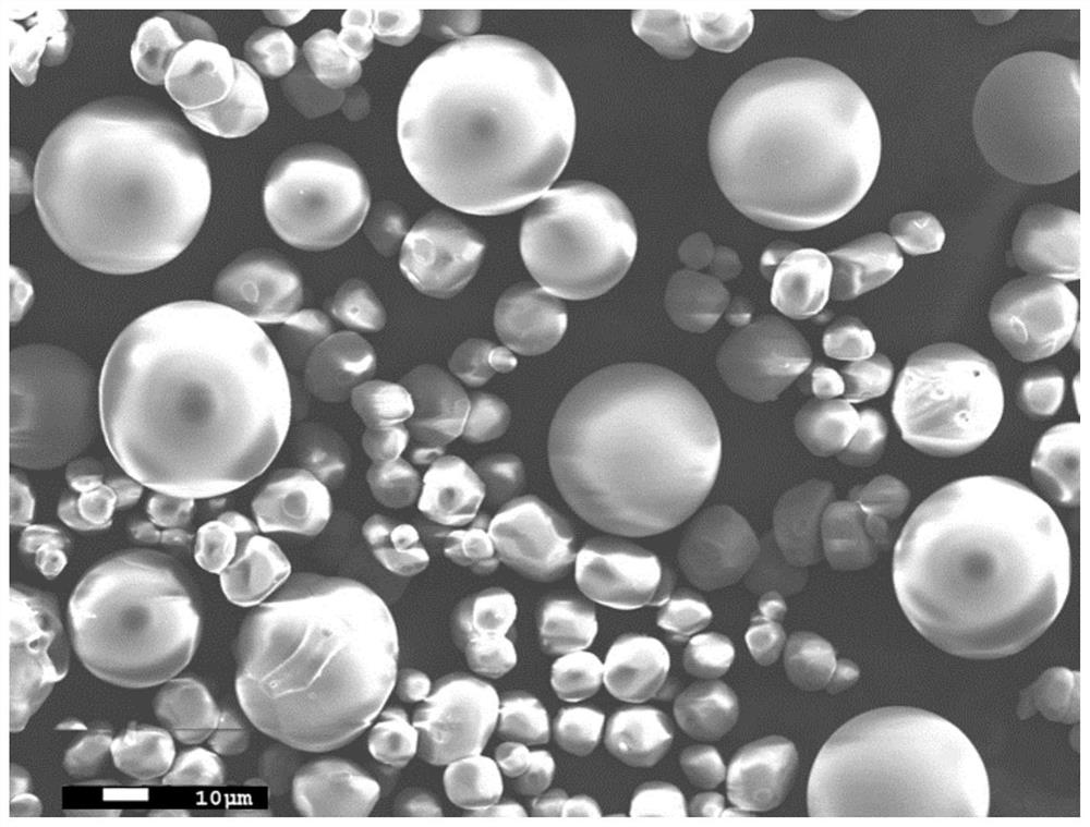
[0040] The preparation method and equipment of the spherical fluorescent single crystal particles of the present invention are described below, specifically as Figure 9 As shown, the present invention adopts the hydrogen flame melting method to prepare spherical fluorescent single crystal particles. The equipment used includes a barrel and a reaction barrel. The barrel is mainly used to accommodate raw material powder for phosphor powder. The barrel includes a powder outlet. Specifically , The particle size range of phosphor raw material powder is 2-20um. The above-mentioned reaction cylinder includes a powder feed port docked with the powder discharge port of the barrel, so that the phosphor raw material powder in the barrel enters through the powder feed port of the reaction barrel; the reaction barrel also includes an oxygen inlet and a hydrogen inlet. Oxygen and hydrogen in the reaction cylinder react in the combustion zone, providing temperature conditions for the liquef...

Embodiment 1

[0052] Prepare the YAG-Al of this embodiment according to the following steps 2 o 3 Fluorescent ceramics.

[0053] S1: Preparation of spherical fluorescent single crystal particles

[0054] It should be noted that the degree of powder liquefaction and the size of droplets can be controlled by controlling the temperature of the combustion zone and by controlling the injection quantity and injection speed of the raw material powder into the combustion zone, so as to control the particle size of the spherical fluorescent single crystal particles. size.

[0055] S2: Preparation of raw material powder for fluorescent ceramics

[0056] Raw materials: high-purity ultra-fine Al 2 o 3 Nano powder, the powder particle size is 0.05-1um, preferably 0.08-0.2um; select high-purity ultra-fine Y 2 o 3 Nano-powder with a particle size of 0.05-0.1um; high-purity ultra-fine MgO nano-powder with a particle size of 0.05-0.1um; YAG: Ce spherical fluorescent single crystal particles prepared ...

Embodiment 2

[0064] Prepare the YAG-Al of this embodiment according to the following steps 2 o 3 Fluorescent ceramics.

[0065] S1: Prepare YAG:Ce spherical fluorescent single crystal particles according to the method for preparing spherical fluorescent single crystal particles in step S1 in Example 1, preferably with a particle size of 30-50um.

[0066] S2: Preparation of raw material powder for fluorescent ceramics

[0067] Weigh Al 2 o 3 Powder, preferably high-purity Al with a particle size of 0.05-1um 2 o 3 Powder, in this embodiment, the commercial Al with a particle size of 0.1-0.2um can be selected as TM-DAR 2 o 3 The powder is selected from the YAG:Ce spherical fluorescent single crystal particles prepared in step S1, wherein Al 2 o 3 The volume ratio of powder to YAG:Ce spherical fluorescent single crystal particles is Al 2 o 3 :YAG=6:4. Will Al 2 o 3The powder and YAG:Ce spherical fluorescent single crystal particle powder are put into a polytetrafluoroethylene bal...


PUM

PropertyMeasurementUnit
particle sizeaaaaaaaaaa
particle diameteraaaaaaaaaa

Abstract

The invention provides a fluorescent ceramic and its preparation method, a light-emitting device and a projection device. The fluorescent ceramic includes an alumina matrix phase and a luminescence center uniformly dispersed in the alumina matrix phase. It is characterized in that the luminescence center is The spherical fluorescent single crystal particle has a smooth spherical outer surface. The spherical fluorescent single crystal particles have a regular spherical shape and a smooth outer surface, so that they can maintain their original appearance after sintering, which is beneficial to the improvement of the structural strength of the fluorescent ceramics after sintering. In addition, the present invention has a larger particle size range The spherical fluorescent single crystal particles can further improve the luminous efficiency of fluorescent ceramics.

Description

technical field [0001] The invention relates to a fluorescent ceramic, in particular to a fluorescent ceramic containing spherical fluorescent single crystal particles, a preparation method thereof, a light emitting device and a projection device. Background technique [0002] With the development of laser display technology, the technology of blue laser excitation of fluorescent materials to obtain visible light has been continuously paid attention to. The current research direction is mainly to develop new fluorescent materials (wavelength conversion materials) based on the characteristics of laser excitation phosphor powder. The main The requirements are high luminous brightness, ability to withstand high-power laser irradiation, high optical conversion efficiency, and high thermal conductivity. [0003] Fluorescent ceramics are ideal for high-power light sources due to their heat resistance and high thermal conductivity. Traditional YAG:Ce pure-phase fluorescent ceramic...

Claims


Application Information

Patent Timeline
Patent Type & Authority Patents(China)
IPC IPC(8): C04B35/10C04B35/622C09K11/80C09K11/02G03B21/20
CPCC04B35/10C04B35/622C04B2235/3206C04B2235/3222C04B2235/3225C04B2235/3229C09K11/025C09K11/7774G03B21/204C09K11/02G03B21/20
Inventor 李乾陈雨叁王艳刚许颜正
Owner APPOTRONICS CORP LTD
Learn More