
Active feeding hopper and feeding method

A feeding and hopper technology, which is applied to the hopper and feeding field of active feeding, can solve the problems of poor stirring uniformity, low success rate of nail suction, affecting the production rhythm of the nail taking mechanism, etc., and achieves convenient maintenance, high feeding efficiency, and reduced design. effect of difficulty

Pending Publication Date: 2020-04-21
无锡丹尼克尔自动化科技有限公司
View PDF0 Cites 6 Cited by
  • Summary
  • Abstract
  • Description
  • Claims
  • Application Information

AI Technical Summary

Problems solved by technology

[0004] Aiming at the problems in the prior art that the bar with hanging head passively relies on the rotation and attraction of the separation plate to stir and be sucked in the hopper, the uniformity of stirring is poor, the success rate of nail suction is low, and the problem that affects the nail-taking mechanism and the follow-up production rhythm, this paper The purpose of the invention is to provide an active feeding hopper and a feeding method with compact structure, stable operation and high working efficiency

Method used


Image

  • Active feeding hopper and feeding method
  • Active feeding hopper and feeding method
  • Active feeding hopper and feeding method

Examples


Embodiment 1

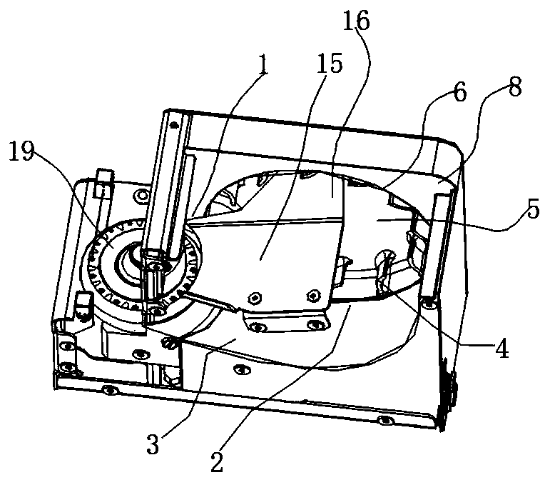
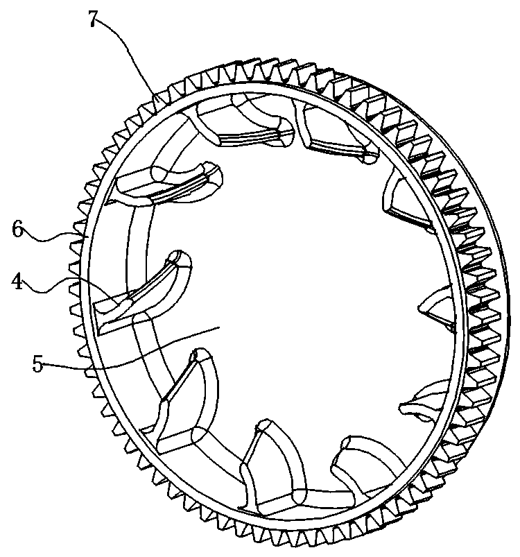
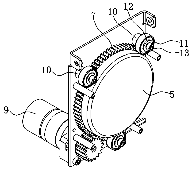
[0036]An active feeding hopper, which is characterized by including a silo, a collecting wheel and a first driving mechanism 9; the silo includes a blanking area 1, a collecting area 2 and an inclined plane 3, and the dropping area 1 is higher than the collecting area 2. The inclined plane 3 connects the blanking area 1 and the collecting area 2; the collecting wheel is connected to the silo at a vertical or inclined predetermined angle, and the collecting wheel is connected to the first driving mechanism 9; the circumferential wall of the collecting wheel 6 The lower edge of the lower edge is arranged in the collecting area 2, and is connected with the edge at the lowest point of the inclined plane 3; several blades 4 are arranged on the circumferential wall 6 of the collecting wheel.

[0037] The aggregate runner includes a bottom surface 5, a peripheral wall 6 connected to the bottom surface 5, a toothed disc 7 is arranged on the outside of the peripheral wall 6; a blade 4 i...

Embodiment 2

[0045] On the basis of embodiment 1, the collection area 2 and the blanking area 1 are set along the axial direction of the collection runner, and the inclined surface 3 is a cylindrical arc surface. At this time, the conveying mechanism 19 is in the axial direction of the collection runner. , the distance from the aggregate runner is relatively long. One end of the feeding slide 15 extends into the collecting wheel, and the other end is arranged above the blanking area 1 close to the conveying mechanism 19. The feeding sliding plate 15 is provided with a number of chutes 18 along the blanking direction. Drop to some chutes 18 on the feeding slide plate 17, drop on the conveying mechanism along the chute 18.


PUM


Abstract

The invention discloses an active feeding hopper and a feeding method. The active feeding hopper is characterized by comprising a stock bin, a material collecting rotating wheel and a first driving mechanism; the stock bin comprises a blanking area, a material collecting area and an inclined plane, the blanking area is higher than the material collecting area, and the inclined plane is connected with the blanking area and the material collecting area; the material collecting rotating wheel is connected with the stock bin at a vertical or inclined set angle and is connected with a first drivingmechanism; a lower edge of a circumferential wall of the material collecting rotating wheel is arranged in the material collecting area and connected with a lowest edge of a slope; and a plurality ofblades are arranged on the circumferential wall of the material collecting rotating wheel. The active feeding hopper and the feeding method have the advantages of being compact in structure, stable in operation and high in working efficiency.

Description

technical field [0001] The invention belongs to the technical field of material conveying, and in particular relates to a hopper and a feeding method for actively feeding materials such as screws and rivets with hanging heads during the conveying process. Background technique [0002] The assembly of screws has developed from the traditional manual tightening to the current automatic screw machine, and the work efficiency has been increased by hundreds or thousands of times. The automatic screw machine includes a screw arrangement machine, a screw alignment machine, a screw feeder, etc. The main function is to transport the screws to the predetermined nail removal position. In the prior art, there is provided a separation and supply device for bars with heads. This separation and supply device has: a hopper that can store many screws and other heads with heads; it is installed at the bottom of the hopper and can be horizontal to inclined With a predetermined angle and free ...

Claims


Application Information

Patent Timeline
IPC IPC(8): B65D88/28B65G47/14
CPCB65D88/28B65G47/1407
Inventor 汪洋
Owner 无锡丹尼克尔自动化科技有限公司
Learn More