Servo main shaft feedback mechanism and numerical control machine tool

A spindle and bushing technology, which is applied in the direction of automatic control devices, metal processing machinery parts, measuring/indicating equipment, etc., can solve problems such as inconsistent rotation angles, affect product processing quality, and cannot accurately control the rotation angle of the working end, etc., to improve Processing quality, practical effect

Active Publication Date: 2020-04-21
HUNAN ZDCY (ZHONGDA CHUANG YUAN) CNC EQUIP CO LTD
View PDF13 Cites 0 Cited by
  • Summary
  • Abstract
  • Description
  • Claims
  • Application Information

AI Technical Summary

Problems solved by technology

However, due to the heavy weight of the working end (or executing end), in the process of driving the working end (or executing end) to rotate through the main shaft 200, one end of the working end (or executing end) installed on the main shaft 200 is connected to the drive. There will be a certain twist at one end of the grating detection device 600, so the detection value of the grating detection device 600 is not consistent with the actual rotation angle of the working end (or execution end), and the rotation angle of the working end (or execution end) cannot be precisely controlled. In the CNC machine tool, the processing quality of the product will be affected, and even the working end (or executing end) of the spindle 200 will interfere with the working end (or executing end) of the other spindle 200.

Method used


Image

  • Servo main shaft feedback mechanism and numerical control machine tool
  • Servo main shaft feedback mechanism and numerical control machine tool
  • Servo main shaft feedback mechanism and numerical control machine tool

Examples


Embodiment Construction

[0026] Embodiments of the present invention are described in detail below, examples of which are shown in the drawings, wherein the same or similar reference numerals designate the same or similar elements or elements having the same or similar functions throughout. The embodiments described below by referring to the figures are exemplary only for explaining the present invention and should not be construed as limiting the present invention.

[0027] In the description of the present invention, it should be understood that the orientation descriptions, such as up, down, front, back, left, right, etc. indicated orientations or positional relationships are based on the orientations or positional relationships shown in the drawings, and are only In order to facilitate the description of the present invention and simplify the description, it does not indicate or imply that the device or element referred to must have a specific orientation, be constructed and operated in a specific ...


PUM


Abstract

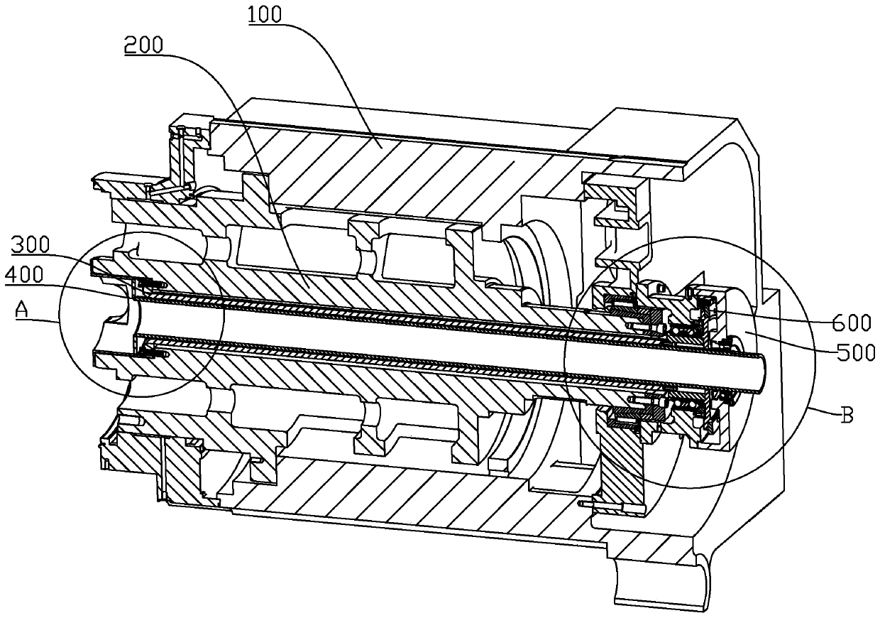
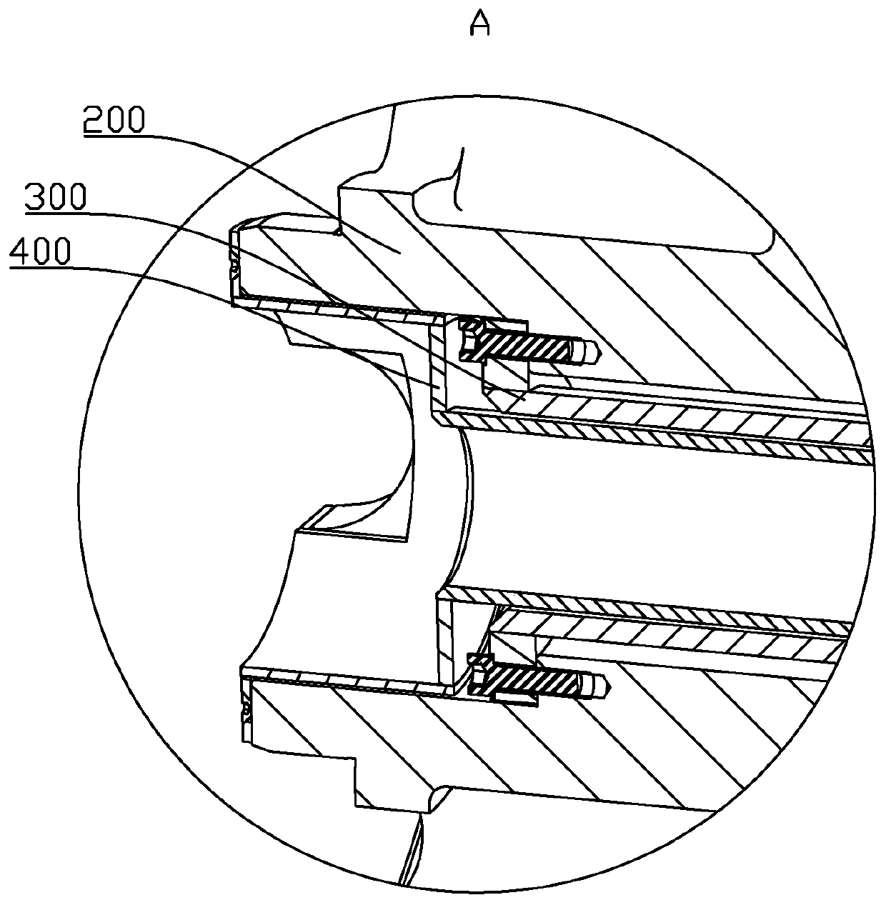
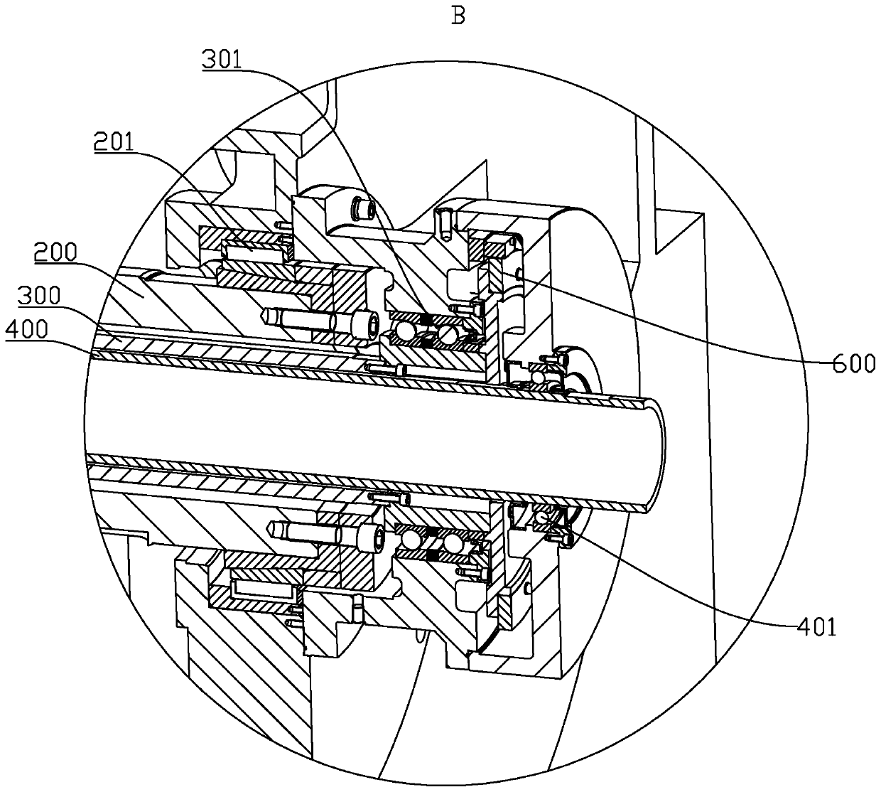
The invention provides a servo main shaft feedback mechanism and a numerical control machine tool. The numerical control machine tool is provided with the servo main shaft feedback mechanism. The servo main shaft feedback mechanism comprises a main shaft, a driving device, a first shaft sleeve and a grating detection device, wherein the main shaft is rotatably installed on a base, and an axis of the main shaft is hollow; the driving device is in transmission connection with one end of the main shaft; one end of the first shaft sleeve is fixedly connected with one end, far away from the drivingdevice, of the main shaft, and the other end penetrates through an axis of the main shaft and extends to the other end of the main shaft; and the grating detection device is used for detecting rotation of one end, extending out of the main shaft, of the first shaft sleeve. The grating detection device in the servo main shaft feedback mechanism detects a rotation angle of the first shaft sleeve. When a working end or an executing end is installed at one end, away from the driving device, of the main shaft, the first shaft sleeve directly feeds back the rotating angle of the working end or theexecuting end, a problem that grating detection precision is affected by main shaft torsion can be effectively solved, and practicability is high.

Description

technical field [0001] The invention relates to the technical field of spindle transmission, in particular to a servo spindle feedback mechanism and a numerically controlled machine tool using the servo spindle feedback mechanism. Background technique [0002] Spindle transmission is one of the most important components in the mechanical field, especially in CNC machine tools. Such as Figure 4 As shown, the main shaft 200 is usually rotatably mounted on a base 100 through multiple sets of bearings, a working end (or execution end) that rotates synchronously with the main shaft 200 is provided at one end of the main shaft 200, and a Drive, drive the main shaft 200 to rotate through the drive, and then drive the working end (or execution end) to rotate. In order to precisely control the rotation angle of the working end (or execution end), a grating detection device 600 is generally installed at the end of the main shaft 200 away from the working end (or execution end), and ...

Claims


Application Information

Patent Timeline
IPC IPC(8): B23Q15/08B23Q17/24
CPCB23Q15/08B23Q17/24
Inventor 张春晖尚吉顺
Owner HUNAN ZDCY (ZHONGDA CHUANG YUAN) CNC EQUIP CO LTD
Why Eureka
Try Eureka