
Control method, control device, PFC circuit, motor driving equipment and air conditioner

A control method and technology of a control device, which can be applied to control electromechanical brakes, control generators, control electromechanical transmission devices, etc., can solve problems such as current distortion, control error, and switch tube damage, so as to solve current distortion and heating problems, improve The effect of job reliability

Active Publication Date: 2020-04-17
广东希塔变频技术有限公司
View PDF6 Cites 4 Cited by
  • Summary
  • Abstract
  • Description
  • Claims
  • Application Information

AI Technical Summary

Problems solved by technology

[0003] The purpose of the present invention is to provide a control method to solve the problem that the switch tube is damaged or the current distortion is caused by the control error when the three-phase PFC circuit based on the VIENNA rectifier is controlled. , control devices, PFC circuits, motor drive equipment and air conditioners

Method used


Image

  • Control method, control device, PFC circuit, motor driving equipment and air conditioner
  • Control method, control device, PFC circuit, motor driving equipment and air conditioner
  • Control method, control device, PFC circuit, motor driving equipment and air conditioner

Examples


Embodiment Construction

[0056] Specific embodiments of the present invention will be described in detail below in conjunction with the accompanying drawings. It should be understood that the specific embodiments described here are only used to illustrate and explain the present invention, and are not intended to limit the present invention.

[0057]It should be noted that if there is a directional indication (such as up, down, left, right, front, back...) in the embodiment of the present invention, the directional indication is only used to explain the position in a certain posture (as shown in the accompanying drawing). If the specific posture changes, the directional indication will also change accordingly.

[0058] In addition, if there are descriptions involving "first", "second" and so on in the embodiments of the present invention, the descriptions of "first", "second" and so on are only for descriptive purposes, and should not be understood as indicating or implying Its relative importance or...


PUM


Abstract

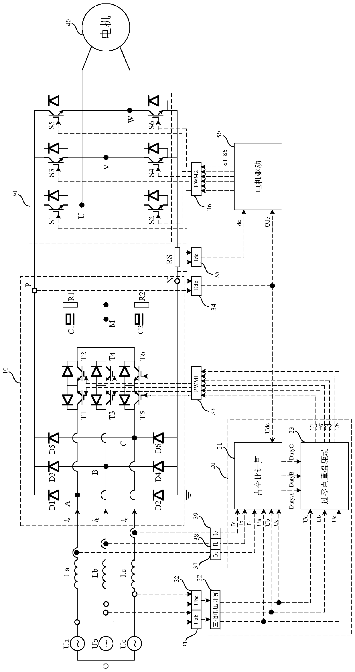
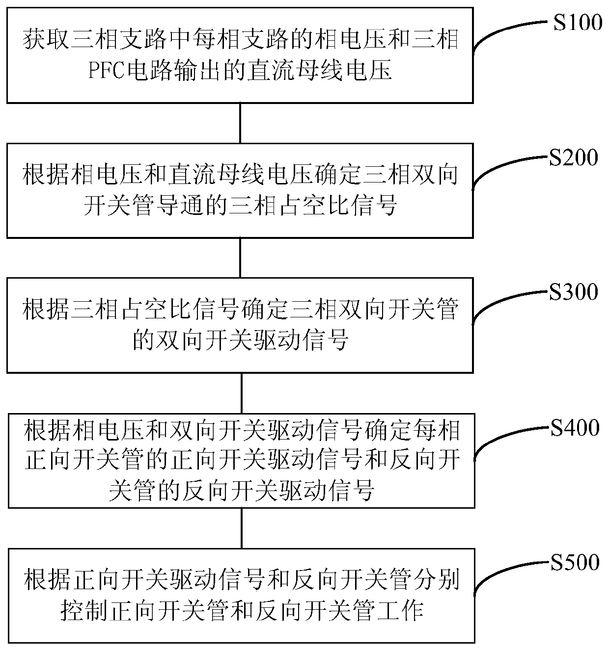
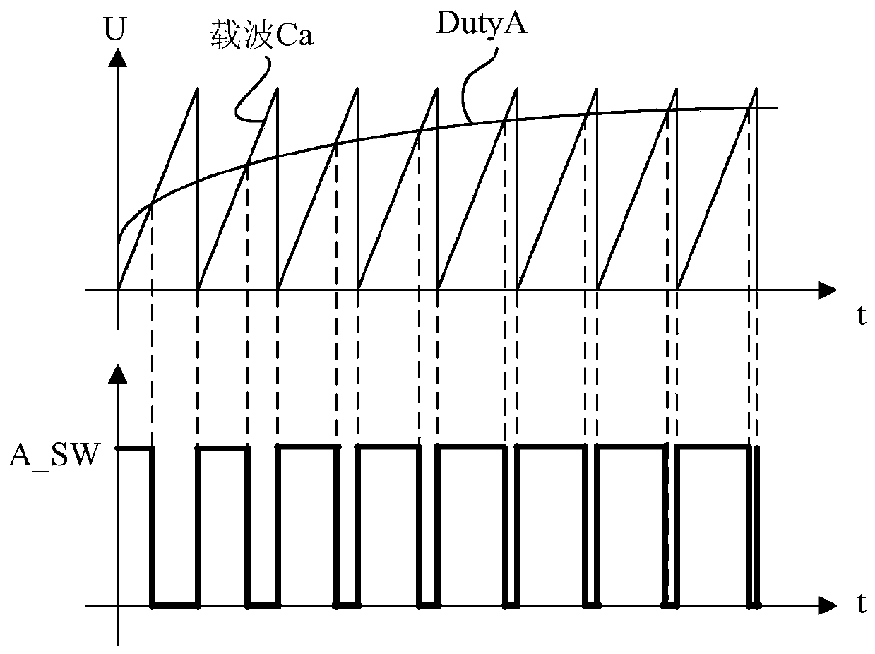
The invention relates to the field of PFC control and discloses a control method, a control device, a PFC circuit, motor driving equipment and an air conditioner. A phase voltage of each phase branchand a direct current bus voltage output by a three-phase PFC circuit are detected, a three-phase duty ratio signal conducted by a three-phase bidirectional switch tube is determined according to the phase voltage of each phase branch and the direct current bus voltage; a bidirectional switch driving signal of the three-phase bidirectional switch tube is determined according to the three-phase dutyratio signal; a forward switch driving signal of a forward switch tube and a reverse switch driving signal of a reverse switch tube of each phase are determined according to the phase voltage and thebidirectional switch driving signal, and finally, the forward switch tube and the reverse switch tube are respectively controlled to work according to the forward switch driving signal and the reverse switch tube. The problems that in a full-conduction scheme in the prior art, a switch tube such as an IGBT generates much heat and has reverse conduction risks are solved, and the problem of currentdistortion in a complementary conduction mode in the prior art is solved, so that the working reliability of the whole three-phase PFC circuit is improved.

Description

technical field [0001] The invention relates to the field of PFC control, in particular to a control method, a control device, a PFC circuit, a motor drive device and an air conditioner. Background technique [0002] When the three-phase PFC circuit based on the VIENNA rectifier is applied, the control method adopted is generally the full conduction mode or the complementary conduction mode. The full conduction mode means that all the three-phase bidirectional switches in the circuit are turned on. When this control method is used to work, the switch tube has a large heat generation and the risk of reverse conduction, resulting in damage to the switch tube. When the complementary conduction is performed, each switch tube of each phase is separately conducted when the voltage of the phase is forward or reverse. When controlling, there are factors such as delay at the zero crossing point, filter processing, and DC bias, which may easily cause voltage The misjudgment of the po...

Claims


Application Information

Patent Timeline
Patent Type & Authority Applications(China)
IPC IPC(8): H02M1/42H02M1/088H02P27/08H02P21/22H02P21/24H02P21/18
CPCH02M1/4216H02M1/088H02M1/083H02P27/08H02P21/22H02P21/24H02P21/18H02P21/0089Y02B70/10
Inventor 盛爽郑长春黄勇王甫敬
Owner 广东希塔变频技术有限公司
Learn More