
A kind of flip-chip interconnection structure and preparation method thereof

An interconnection structure and flip-chip technology, which is applied in semiconductor/solid-state device manufacturing, semiconductor/solid-state device parts, semiconductor devices, etc., can solve problems such as signal crosstalk and difficult process, so as to increase the connection height and reduce the difficulty of process Effect

Active Publication Date: 2021-12-24
THE 13TH RES INST OF CHINA ELECTRONICS TECH GRP CORP
View PDF9 Cites 0 Cited by
  • Summary
  • Abstract
  • Description
  • Claims
  • Application Information

AI Technical Summary

Problems solved by technology

[0005] In view of this, the present invention provides a flip-chip interconnection structure and its preparation method to solve the difficulty in the 3D stacking integration process of chips using solder bumps in the prior art, while using metal bumps for 3D stacking of chips Integration has the problem of signal crosstalk

Method used


Image

  • A kind of flip-chip interconnection structure and preparation method thereof
  • A kind of flip-chip interconnection structure and preparation method thereof
  • A kind of flip-chip interconnection structure and preparation method thereof

Examples


Embodiment Construction

[0042] In the following description, specific details such as specific system structures and technologies are presented for the purpose of illustration rather than limitation, so as to thoroughly understand the embodiments of the present invention. It will be apparent, however, to one skilled in the art that the invention may be practiced in other embodiments without these specific details. In other instances, detailed descriptions of well-known systems, devices, circuits, and methods are omitted so as not to obscure the description of the present invention with unnecessary detail.

[0043] In order to make the purpose, technical solution and advantages of the present invention clearer, specific embodiments will be described below in conjunction with the accompanying drawings.

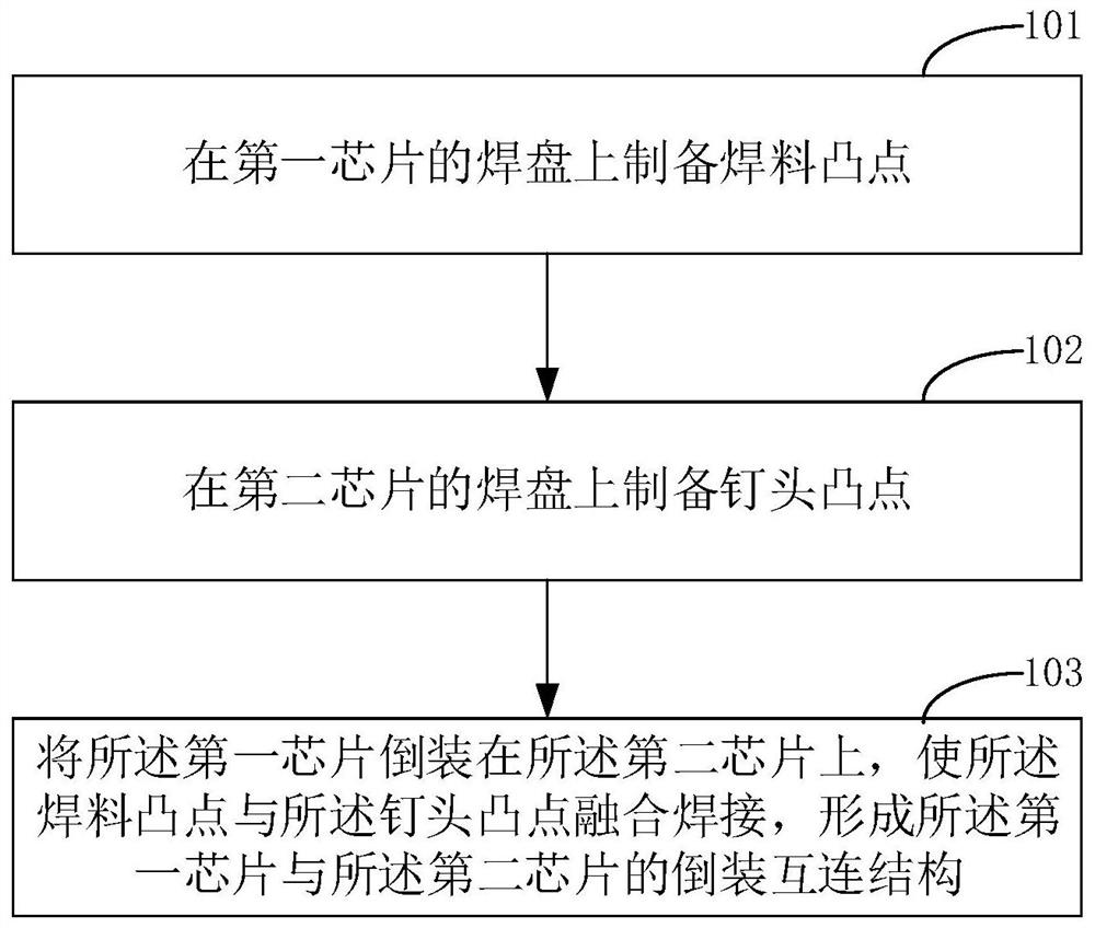
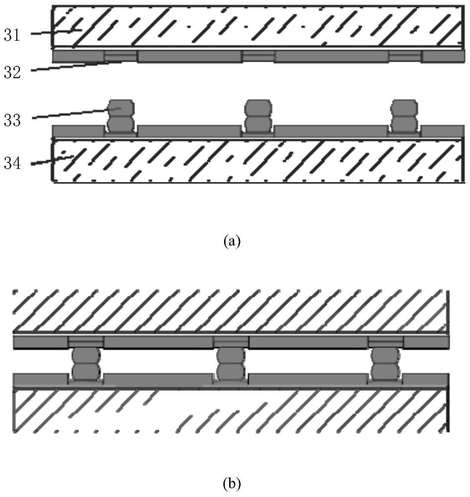
[0044] see figure 1 , which shows the implementation flowchart of the method for preparing the flip-chip interconnection structure provided by the embodiment of the present invention, which is used to...


PUM


Abstract

The present invention is applicable to the field of flip-chip technology, and provides a method for preparing a flip-chip interconnection structure, which is used to realize flip-chip interconnection between a first chip and a second chip, wherein the preparation method includes: preparing solder bumps on the pads of the chip; preparing stud bumps on the pads of the second chip; flipping the first chip onto the second chip so that the solder bumps are aligned with the nails The head bumps are fused and welded to form a flip-chip interconnection structure between the first chip and the second chip. The preparation method provided by the present invention does not need to accurately control the thickness of electroplated solder bumps or copper pillars, which reduces the difficulty of the process; and increases the connection height between chips, which can make it difficult to generate signal crosstalk and difficult to form between the upper and lower chips. Small cavity resonance realizes the application of metal bumps in high-frequency and high-speed chip 3D stacking integration.

Description

technical field [0001] The invention belongs to the technical field of flip chips, and in particular relates to a flip chip interconnection structure and a preparation method thereof. Background technique [0002] With the continuous extension of Moore's Law, the size of chip technology devices is getting smaller and smaller, and integrated circuit chips have a higher degree of integration. However, when the size of the device reaches the deep submicron scale, it becomes more and more difficult to further reduce it. The research on chip design begins to develop in a three-dimensional direction, and chip stack packaging technology appears. [0003] Chip stack packaging technology requires the use of narrow-pitch (bump pitch less than 200 microns) flip-chip bonding method for soldering between chips. In the prior art, solder bumps are usually used for flip-chip bonding between chips. For example, in the chip Solder bumps are formed by electroplating a solder layer on the surf...

Claims


Application Information

Patent Timeline
Patent Type & Authority Patents(China)
IPC IPC(8): H01L21/60H01L21/607H01L23/488
CPCH01L24/81H01L24/16H01L2224/81203H01L2224/81205H01L2224/8134H01L2224/81801H01L2224/16135H01L2224/16145
Inventor 杨彦锋徐达常青松张延青任若松刘晓红崔玉发任健吉红霞苏辰飞王云飞郭丰强马伟宾
Owner THE 13TH RES INST OF CHINA ELECTRONICS TECH GRP CORP
Learn More