
A hybrid projection objective lens, projection exposure equipment and imaging system

A technology of projection objective lens and imaging system, which is applied in microlithography exposure equipment, photomechanical equipment, exposure device of photo-plate making process, etc. It can solve the problem that the design of objective lens cannot meet the actual demand, and achieve uniform pupil apodization and good imaging The effect of small resolution and incident angle

Active Publication Date: 2021-05-14
CHANGCHUN INST OF OPTICS FINE MECHANICS & PHYSICS CHINESE ACAD OF SCI
View PDF4 Cites 0 Cited by
  • Summary
  • Abstract
  • Description
  • Claims
  • Application Information

AI Technical Summary

Problems solved by technology

Therefore, the objective lens design of the second technology (reflection imaging technology) can no longer meet the actual needs

Method used


Image

  • A hybrid projection objective lens, projection exposure equipment and imaging system
  • A hybrid projection objective lens, projection exposure equipment and imaging system
  • A hybrid projection objective lens, projection exposure equipment and imaging system

Examples


Embodiment Construction

[0034] The following will clearly and completely describe the technical solutions in the embodiments of the present invention with reference to the accompanying drawings in the embodiments of the present invention. Obviously, the described embodiments are only some, not all, embodiments of the present invention.

[0035] In the description of the present invention, unless otherwise stated, the meaning of "plurality" is two or more; the terms "upper", "lower", "left", "right", "inner", "outer" , "front end", "rear end", "head", "tail", etc. indicate the orientation or positional relationship based on the orientation or positional relationship shown in the drawings, and are only for the convenience of describing the present invention and simplifying the description, rather than Nothing indicating or implying that a referenced device or element must have a particular orientation, be constructed, and operate in a particular orientation should therefore not be construed as limiting ...


PUM


Abstract

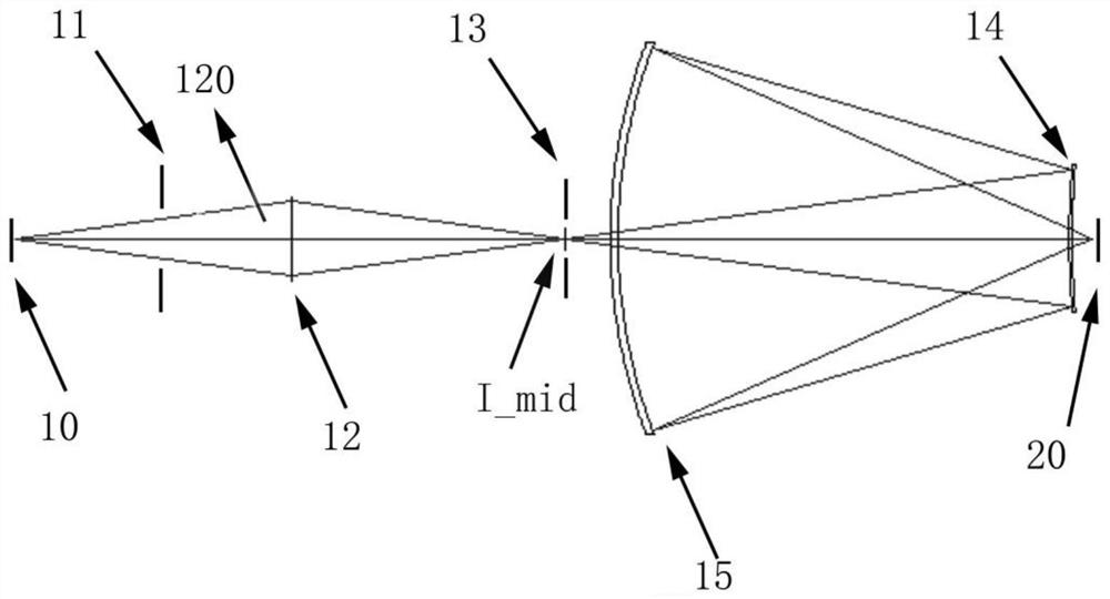
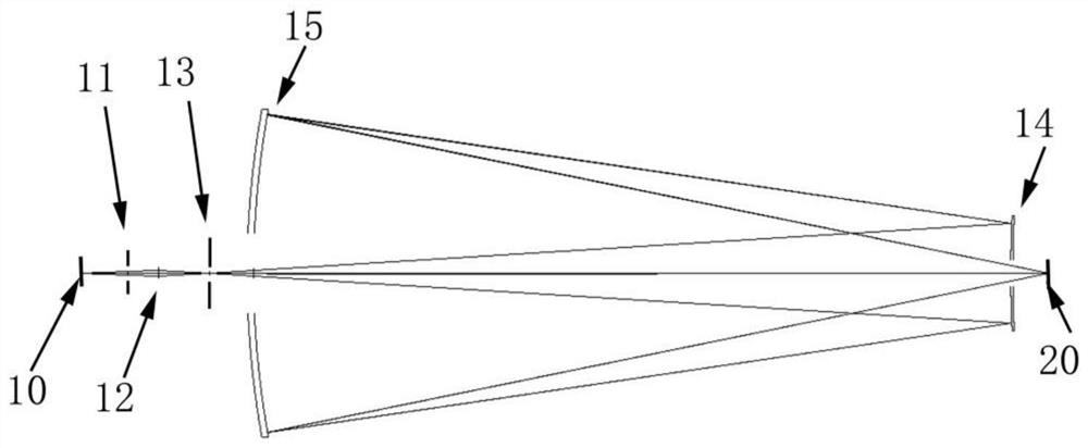
The invention relates to a hybrid projection objective lens, projection exposure equipment and an imaging system. The hybrid projection objective lens includes: a first reflector and a second reflector arranged between the object plane and the image plane; An aperture stop, a secondary imaging compensation diffraction element and a field stop are arranged in sequence between the mirrors. The beneficial effects of the present invention are that the imaging field of view of the present invention is larger, the numerical aperture is higher, and the resolution is higher, and the incident angle of the light in the present invention on the reflector is smaller, and the reflectivity due to the change of the incident angle The impact received is smaller, so that the optical system is easy to achieve a more uniform pupil apodization in the entire imaging aperture. In addition, the diaphragm is not arranged on the spherical center of the mirror in the present invention, but between the object plane and the diffraction element. An aperture stop is set at an appropriate position between them, so that the optical path of the imaging system meets the requirements of the telecentric optical path of the image plane.

Description

technical field [0001] The invention relates to the technical field of optical design, in particular to a hybrid projection objective lens, projection exposure equipment and an imaging system. Background technique [0002] In 1895, German scientist Roentgen discovered X-rays while experimenting with cathode ray tubes. Since then, many people have been attracted to study X-ray imaging. People have mainly studied the following two technologies for imaging systems of ultra-short-wavelength rays such as X-rays: [0003] The first is diffractive imaging technology. Diffractive optical elements are widely used in the field of X-ray imaging due to their high design freedom, wide material selectivity, flexible wavefront transformation, and suitability for array production. The resolution X-ray imaging device uses a diffraction element as an imaging element, but due to the limitation of processing technology, the difficulty of processing a higher resolution diffraction element increa...

Claims


Application Information

Patent Timeline
Patent Type & Authority Patents(China)
IPC IPC(8): G03F7/20
CPCG03F7/70233G03F7/70258G03F7/70316
Inventor 刘涛张新王灵杰史广维付强
Owner CHANGCHUN INST OF OPTICS FINE MECHANICS & PHYSICS CHINESE ACAD OF SCI
Learn More