
Portable direct-current power supply system loop detection method and device

A technology of DC power system and loop detection, which is applied in the direction of power supply testing, etc., and can solve problems such as the inability to determine the type and location of loop faults, affecting the safe production of the power grid, and the difficulty of loop fault detection.

Pending Publication Date: 2020-04-17
SHANGQIU POWER SUPPLY CO OF STATE GRID HANAN ELECTRIC POWER CO
View PDF11 Cites 1 Cited by
  • Summary
  • Abstract
  • Description
  • Claims
  • Application Information

AI Technical Summary

Problems solved by technology

[0005] The present invention provides a portable DC power system loop detection method and its device, capable of performing real-time loop detection regardless of whether there is current in the DC power system, accurately locating loop faults and determining the type of loop faults, reducing The advantages of the difficulty of finding loop faults are solved, and the current detection of loop faults in the two sets of DC power systems is indirectly reflected by the operator through the abnormality of other equipment, and the specific cause of the loop fault cannot be determined The type and location of occurrence will increase the loop fault processing time, seriously affecting the safe and reliable operation of the substation, and even affect the safe production of the entire power grid, and determine the loop of the DC power supply through the abnormality of other equipment Faults are greatly affected by the device itself, and it is difficult to detect loop faults

Method used


Image

  • Portable direct-current power supply system loop detection method and device
  • Portable direct-current power supply system loop detection method and device
  • Portable direct-current power supply system loop detection method and device

Examples


Embodiment Construction

[0042]The following will clearly and completely describe the technical solutions in the embodiments of the present invention with reference to the accompanying drawings in the embodiments of the present invention. Obviously, the described embodiments are only some, not all, embodiments of the present invention. Based on the embodiments of the present invention, all other embodiments obtained by persons of ordinary skill in the art without making creative efforts belong to the protection scope of the present invention.

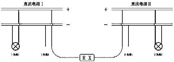
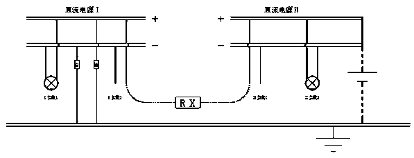
[0043] see Figure 1-2 , a portable DC power system loop detection, including two detection modes: bridge test method and injection signal detection method. The bridge test method is mainly used for non-stop detection of DC power supply systems. The bridge test method has the following two groups of implementations Program:

[0044] Implementation Plan A

[0045] S1. Close the switch K1, turn off the switch K2, put the unbalanced resistor R2 in the positive p...


PUM


Abstract

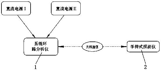
The invention discloses a portable direct-current power supply system loop detection method and device. The detection method comprises a bridge test method and an injection signal detection method. The bridge test method is mainly applied to uninterrupted detection of a direct-current power supply system, the injection signal detection method is mainly applied to outage detection of the direct-current power supply system, and the injection signal detection method detects positive and negative voltages to ground, frequency and the like of a direct-current power supply I after injecting signalsinto a direct-current power supply II and compares the voltages to ground and the frequency with those of the direct-current power supply II during signal injection. The detection device comprises a system loop analyzer and a handheld detector. According to the portable direct-current power supply system loop detection method and device, the bridge test method and the injection signal detection method are combined, no matter whether two independent direct-current power supply systems have electricity or not, the loop condition of the direct-current power supply systems can be detected, and meanwhile, a loop fault point can be quickly positioned by adopting a wireless communication technology, so that the workload of the detection personnel is effectively reduced, and the direct-current loop fault finding difficulty is reduced.

Description

technical field [0001] The invention belongs to the technical field of circuit detection devices, and in particular relates to a portable DC power supply system loop detection method and a device thereof. Background technique [0002] At present, in power plants, 220KV level and above, and some important 110KV substations, the important loads are powered by two relatively independent DC power supplies, and any set of DC power supplies is selected for power supply through the open circuit, and in There is a bus tie switch between the busbars connecting two sets of DC power supplies. When one of the power supplies is in a charging state or fails or other accidents, the other set of power supply equipment can be used for power supply in time, so as to ensure the reliability of power supply. be greatly improved. [0003] However, in the process of new construction or equipment renovation, due to factors such as large changes in equipment, insulation reduction, or personnel miso...

Claims


Application Information

Patent Timeline
IPC IPC(8): G01R31/40
CPCG01R31/40
Inventor 刘柏源朱辉张勇徐振高方张桂晨刘乾鹏
Owner SHANGQIU POWER SUPPLY CO OF STATE GRID HANAN ELECTRIC POWER CO
Learn More