
Mold with rapid cooling function and convenient mold taking for bearing machining

A rapid cooling and bearing processing technology, applied in the field of bearing processing, can solve problems such as troublesome assembly, affecting the injection molding process, and slow mold cooling speed, and achieve the effects of easy mold taking, enhanced sealing, and accelerated heat dissipation process

Inactive Publication Date: 2020-04-17
东莞市史雷帝三维数控科技有限公司
View PDF0 Cites 2 Cited by
  • Summary
  • Abstract
  • Description
  • Claims
  • Application Information

AI Technical Summary

Problems solved by technology

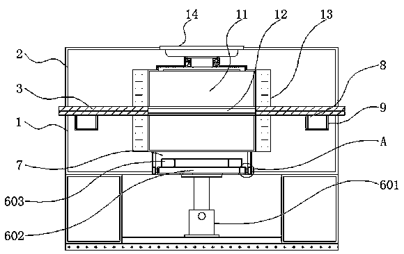
[0004] The object of the present invention is to provide a mold with rapid cooling for easy mold taking for bearing processing, so as to solve the problem that the existing bearing processing molds proposed in the above background technology are generally cumbersome to assemble, and the cooling speed of the mold is relatively slow. The mold does not have a corresponding ejection structure, which makes it difficult to take out the mold, and the position of the injection port does not have effective heat preservation measures.

Method used


Image

  • Mold with rapid cooling function and convenient mold taking for bearing machining
  • Mold with rapid cooling function and convenient mold taking for bearing machining
  • Mold with rapid cooling function and convenient mold taking for bearing machining

Examples


Embodiment Construction

[0026] The technical solutions in the embodiments of the present invention will be clearly and completely described below in conjunction with the accompanying drawings in the embodiments of the present invention. Obviously, the described embodiments are only some of the embodiments of the present invention, not all of them. Based on The embodiments of the present invention and all other embodiments obtained by persons of ordinary skill in the art without making creative efforts belong to the protection scope of the present invention.

[0027] In the description of the present invention, unless otherwise stated, the meaning of "plurality" is two or more; the terms "upper", "lower", "left", "right", "inner", "outer" , "front end", "rear end", "head", "tail", etc. indicate the orientation or positional relationship based on the orientation or positional relationship shown in the drawings, and are only for the convenience of describing the present invention and simplifying the desc...


PUM


Abstract

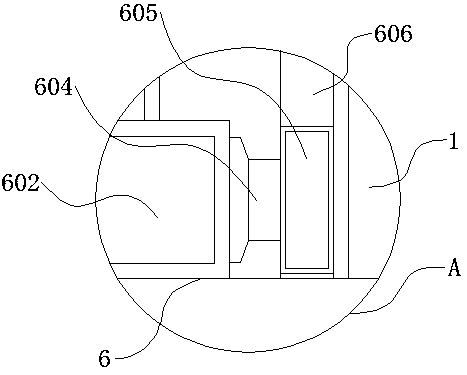
The invention discloses a mold with a rapid cooling function and convenient mold taking for bearing machining, and relates to the technical field of bearing machining. The mold comprises a lower mold,a mold cavity and a cooling mechanism, wherein an upper mold is arranged above the lower mold, and a rubber attaching layer is arranged on the outer side of the joint of the upper mold and the lowermold; supporting columns are fixed on the two sides of the lower part of the lower mold, and an anti-skid bottom plate is arranged at the bottoms of the supporting columns; an ejection mechanism is arranged above the middle of the anti-skid bottom plate, and an ejection groove is formed in the middle of the lower part of the lower mold; and clamping blocks are fixed below the four corners of the upper mold, and clamping grooves are formed in the four corners of the lower mold. The mold has the beneficial effects that the ejection mechanism is arranged, so that a formed bearing can be conveniently ejected out to be loosened so as to be convenient to take; and an electric telescopic rod is arranged, so that a push plate and an ejection block can be conveniently driven to ascend and descend,and therefore the formed bearing can be conveniently ejected out, and the ejection block is of an annular structure and is matched with the shape of the mold cavity of the bearing.

Description

technical field [0001] The invention relates to the technical field of bearing processing, in particular to a mold for bearing processing with rapid cooling and convenient mold taking. Background technique [0002] Bearing is an important part of contemporary mechanical equipment. Its main function is to support the mechanical rotating body, reduce the friction coefficient during its movement, and ensure its rotation accuracy. In the process of bearing processing, it is necessary to use molds to make it preliminary Molding refers to various molds and tools used in industrial production for injection molding, blow molding, extrusion, die-casting or forging forming, smelting, stamping and other methods to obtain the required products. [0003] The existing molds for bearing processing are generally cumbersome to assemble, and the cooling speed of the mold is relatively slow. The formed mold does not have a corresponding ejection structure, which makes it difficult to take the ...

Claims


Application Information

Patent Timeline
Patent Type & Authority Applications(China)
IPC IPC(8): B29C45/26B29C45/27B29C45/40B29C45/73B29L31/04
CPCB29C45/2602B29C45/27B29C45/2708B29C45/4005B29C45/7312B29L2031/04
Inventor 黄红梅
Owner 东莞市史雷帝三维数控科技有限公司
Learn More