
Dry burning judgment method applied to PTC heating equipment

A heating equipment, dry burning technology, applied in the direction of thermometers, ohmic resistance heating, ohmic resistance heating circuit diagrams that use electrical/magnetic components directly sensitive to heat, etc., can solve problems such as increasing equipment costs, and achieve the effect of reducing costs

Active Publication Date: 2020-04-14
GUANGDONG TONZE ELECTRIC CO LTD
View PDF7 Cites 0 Cited by
  • Summary
  • Abstract
  • Description
  • Claims
  • Application Information

AI Technical Summary

Problems solved by technology

Due to the need to set up special temperature control or temperature measurement devices, the equipment cost is increased

Method used


Image

  • Dry burning judgment method applied to PTC heating equipment
  • Dry burning judgment method applied to PTC heating equipment
  • Dry burning judgment method applied to PTC heating equipment

Examples


Embodiment 1

[0040] In the present embodiment, the dry burning judgment method applied to PTC heating equipment is characterized in that:

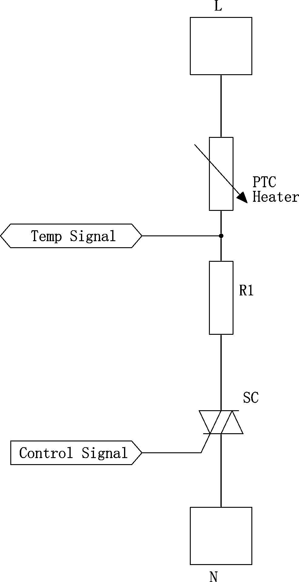
[0041] refer to figure 1 , connect the PTC heating device with the power line and the main control chip in the following way: one end of the PTC heating device (PTCheater) is connected to the live wire L, the other end of the PTC heating device is connected to the end of the resistor R1, and the other end of the resistor R1 is controlled by The silicon SC is connected to the neutral line N; the control pole of the thyristor SC is connected to the corresponding control signal output terminal of the main control chip (the main control chip is not shown in the figure), and the connection between the PTC heating device and the resistor R1 is used as a temperature signal The detection terminal (Temp Signal), the temperature signal detection terminal is connected to the corresponding signal input terminal of the main control chip;

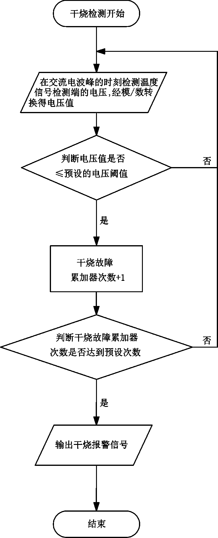
[0042] The main control ...

Embodiment 2

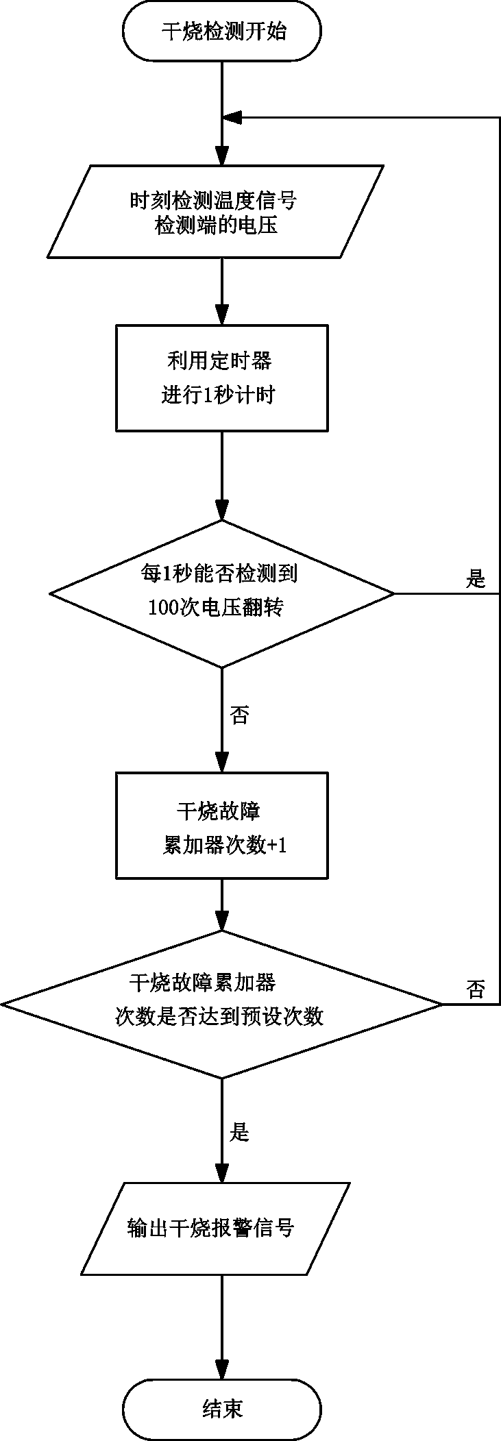
[0058] The circuit connection of this embodiment is the same as that of Embodiment 1. The difference from the embodiment is that in this embodiment, the main control chip does not have an analog / digital converter (that is, the main control chip does not have an analog / digital conversion function. For example, the main control chip can be the chip HT68F003 produced by Holtek. ), the steps to judge whether the PTC heating equipment is in a dry state are as follows:

[0059] (1') Detect the voltage of the temperature signal detection terminal at all times;

[0060] (2') Use the timer to count for 1 second, and judge whether a predetermined number of (such as 100) voltage reversals can be detected every 1 second;

[0061] If the predetermined number of voltage reversals cannot be detected, add 1 to the accumulator of dry burning faults, and enter step (3');

[0062] If a predetermined number of voltage reversals can be detected, return to step (1');

[0063] (3') Judging whethe...


PUM


Abstract

The invention relates to dry burning judgment method applied to PTC heating equipment. The dry burning judgment method is characterized in that one end of PTC heating equipment is connected with a live wire, the other end of the PTC heating equipment is connected with one end of a resistor, and the other end of the resistor is connected with a zero line through a silicon controlled rectifier; a control electrode of the silicon controlled rectifier is connected with a corresponding control signal output terminal of a main control chip, the joint of the PTC heating equipment and the resistor isused as a temperature signal detection terminal, and the temperature signal detection terminal is connected with a corresponding signal input terminal of the main control chip; the main control chip acquires an electric signal of the temperature signal detection terminal, compares the processed electric signal with a preset threshold value, and judges whether the PTC heating equipment is in a dryburning state or not according to a comparison result; and the main control chip sends a signal through the control signal output terminal to control the on-off state of the silicon controlled rectifier so as to control whether the PTC heating equipment is connected with a power supply or not. Whether the PTC heating equipment is in a dry burning state or not can be accurately judged, a special temperature control or temperature measurement device is omitted, so that cost reduction is facilitated.

Description

technical field [0001] The invention relates to the technical field of electric heating equipment, in particular to a method for judging dry burning applied to PTC heating equipment. Background technique [0002] Existing heating equipment generally uses special temperature control or temperature measuring devices (such as thermistors, thermostats, thermocouples, infrared temperature measurement, etc.) to detect the temperature of heated objects (such as containers used to accommodate food materials), By judging whether the temperature has risen abnormally, and then judging whether the heating equipment is in a dry state, and controlling the power supply of the heating equipment to prevent dry burning and accidents. Since special temperature control or temperature measurement devices need to be set, the equipment cost is increased. Contents of the invention [0003] The technical problem to be solved by the present invention is to provide a dry-burning judging method appl...

Claims


Application Information

Patent Timeline
Patent Type & Authority Applications(China)
IPC IPC(8): G01K7/18G01K7/20G01K1/02H05B1/02H05B3/00H05B3/02
CPCG01K7/183G01K7/20G01K1/02H05B1/0202H05B3/0014H05B3/0019H05B3/02
Inventor 詹捷辉詹文杰吕全彬
Owner GUANGDONG TONZE ELECTRIC CO LTD
Learn More